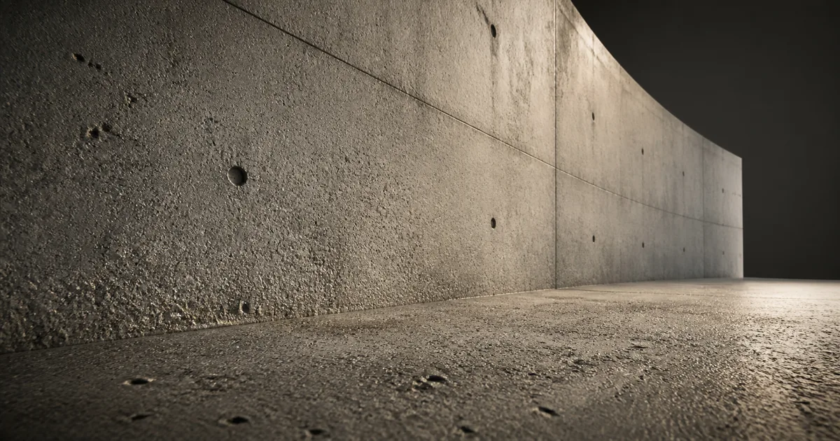
Detail maps solve a very specific material problem: the object looks correct from across the room, then the camera approaches and the surface becomes a soft collection of enlarged pixels. Replacing every base texture with an 8K file is one response. It is also a good way to make the texture budget file a formal complaint.
A detail layer keeps reusable microstructure separate from unique object information. The base maps describe panels, stains, grain direction, large chips, and baked features. A smaller detail texture, tiled many more times, adds pores, fibers, orange peel, fine scratches, or roughness breakup when those features become visible.
This guide explains how detail mapping works, where its limits are, how to combine normal layers without flattening them, and how to keep the result stable in Unity, Unreal Engine, and Blender. The useful target is not “more noise.” It is the right surface information at the scale where a camera can actually read it.
What detail maps actually add to a PBR material
Detail maps are secondary textures with independent tiling and strength. A shader samples them at a finer scale than the base material and combines their values into color, roughness or smoothness, normals, and sometimes masks. Because the same small texture can serve many square metres of surface, it provides close-range definition without storing identical pores in every asset’s unique texture set.
The technique works because material information occupies different spatial frequencies. Broad concrete discoloration may span metres. Formwork marks and chips may span centimetres. Pores may span millimetres. One texture can contain all three, but its resolution and UV coverage force a compromise. PBR detail maps let the broad layer remain broad while the fine layer repeats at a believable physical size.
They do not change the silhouette, create deep parallax, or restore unique features missing from the base map. A tiled pore texture cannot invent a serial number, align a scratch with a corner, or preserve a large crack through a low-resolution bake. Use texture resolution for unique screen-space information, decals for placed details, and geometry or displacement when relief must affect depth or outline.
Separate the material into frequency layers
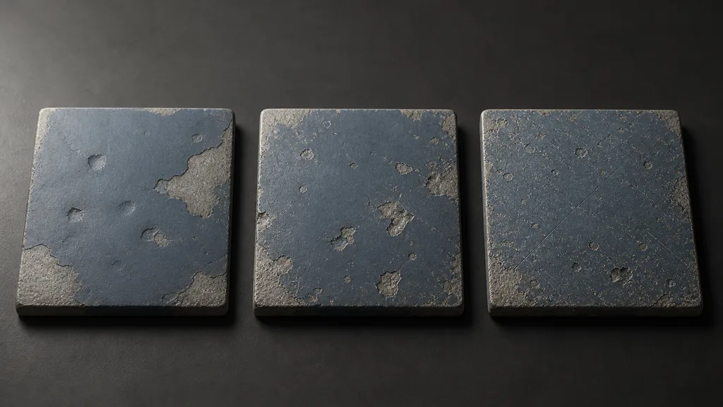
Before authoring detail maps, sort the reference into broad, medium, and fine signals. Broad features define the asset or installation: panel boundaries, knots, slab variation, major wear, large stains. Medium features explain use and manufacture: chips, brush passes, shallow dents, mortar breakup. Fine features describe the substrate: pores, weave, grain cells, sanding lines, or a coating’s orange peel.
| Frequency | Typical content | Best home |
|---|---|---|
| Broad | Large color fields, panels, object-specific damage | Base texture, geometry, decals |
| Medium | Chips, joints, dents, directional wear | Base maps or a controlled material layer |
| Fine | Pores, fibers, tiny grain, shallow scratches | Tileable detail maps |
The split is about repeatability as much as size. Concrete pores can repeat because no single pore carries meaning. A distinctive crescent scratch becomes evidence after its fourth appearance. Remove memorable landmarks from the detail layer, keep direction only when the manufacturing process supports it, and preview a large tiled field before declaring the source reusable.
Build detail maps around neutral values
A clean detail texture modifies the base rather than replacing it. Color detail should hover around a neutral midpoint so it can darken and lighten locally without imposing a second full albedo. Roughness detail should represent genuine micro-surface changes, not a sharpened copy of color. A detail normal map should remain close to flat except where the fine relief changes orientation.
- Detail color: remove broad gradients, lighting, stains, and recognizable shapes; preserve restrained high-frequency variation.
- Detail roughness map: encode small finish changes caused by fibers, pores, abrasion, or coating texture; keep it linear.
- Detail normal map: use tangent-space micro-relief with a consistent Y convention and a clean flat baseline.
- Detail mask texture: identify where the microstructure exists, changes, or is covered by another material layer.
Record physical coverage beside the asset. “Tiling 12” only means something for one mesh and one UV layout. “This 512-pixel tile represents 10 centimetres” can survive reuse, LODs, and a teammate who was not present when the shader graph acquired its seventh multiply node.
Pack compatible grayscale channels when they share UVs, resolution, filtering, and compression needs. Do not pack a tangent-space normal into arbitrary single channels unless the destination format expects it. The channel-packing guide covers why a smaller file is not automatically a valid map family.
Blend detail normal maps without erasing the base
Normal blending is the part of detail mapping most likely to look acceptable in a still and fail under a moving light. Adding RGB values or linearly interpolating two normal textures treats encoded directions like ordinary colors. The result can flatten the base normal, shrink both layers toward the default direction, or produce strength changes that depend on the blend amount.
Use the engine’s established normal-combine function or a tested method such as reoriented normal mapping. The base layer should keep its large slope while the detail layer perturbs that local frame. Normalize the result, keep both maps in the expected tangent convention, and test on a curved object with a rotating area light. The normal map foundations explain why channel orientation and tangent basis matter before any blending begins.
Strength should follow physical scale. A plaster pore may be visible in grazing light without carving a dark crater into the wall. If the layer reads as gravel from an ordinary camera distance, the problem is not insufficient texture resolution. The tiny surface has been promoted beyond its station.
Use detail masks where the surface process changes
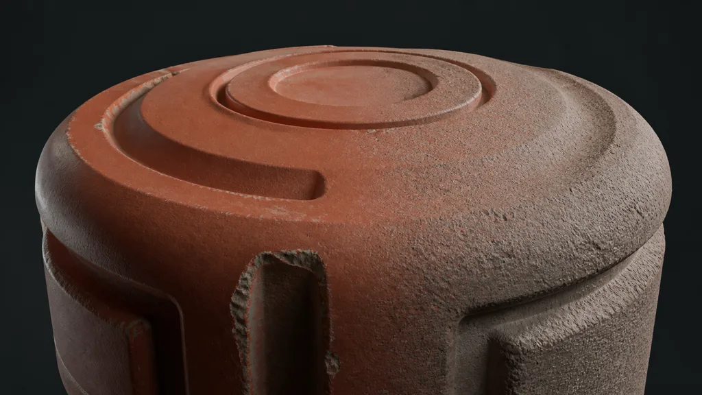
One detail layer rarely belongs everywhere. Skin pores should not continue across lips, cloth weave should stop at rubber trim, and a painted orange-peel normal should disappear where bare metal is exposed. A detail mask texture makes those boundaries explicit.
Derive the mask from material IDs, coating thickness, vertex color, procedural rules, or authored wear. Give transitions enough width to survive mipmapping. A one-pixel hard border can turn into a bright seam as the texture recedes, while an excessively soft mask makes every boundary look airbrushed.
Masks can also vary intensity across an asset, but variation needs a cause: handling polishes a grip, water suppresses dusty pores, paint fills a cast surface, or abrasion cuts across an aligned finish. Random clouds hide repetition for a moment and then become a larger repeated pattern with better public relations.
Control detail texture tiling, mipmaps, and distance
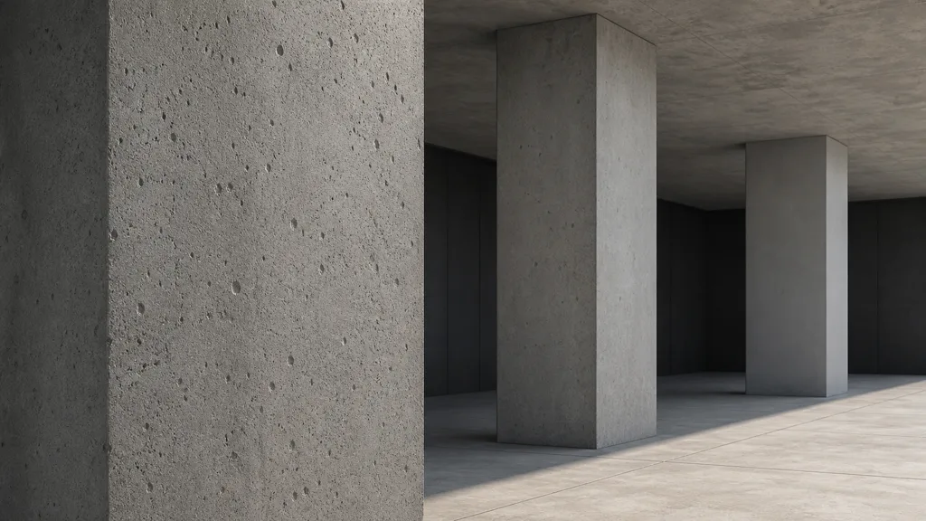
Correct detail texture tiling begins in physical units. Measure a feature in the reference, decide how many centimetres the tile represents, and derive the UV multiplier from object scale. Uniform UV numbers across differently sized assets do not guarantee uniform detail; they merely guarantee consistent arithmetic.
Then test three camera zones. Close views should reveal the intended pores or fibers. Middle views should retain material character without obvious repetition. Far views should allow mipmaps and a controlled fade to remove frequencies that no longer fit inside a pixel. The texture-filtering guide covers the sampling side, while the texture-streaming guide covers residency and mip selection.
A distance fade is not a substitute for valid mipmaps. Use both. Fade strength before high-frequency contrast becomes unstable, avoid a visible ring around the camera, and profile the shader branch or lerp on target hardware. The best detail map workflow 2026 removes a layer when it stops changing the output pixel. Loyalty is not a rendering feature.
Detail maps in Unity, Unreal Engine, and Blender
For detail maps Unity projects, the Built-in Standard Shader exposes secondary albedo and normal maps plus a detail mask. Unity’s current Secondary Maps documentation describes the high-tiling overlay. HDRP uses a packed detail map convention, while URP or custom Shader Graph materials may need an explicit blend path. Confirm the active render pipeline before packing channels, and import numeric detail data without sRGB conversion when its format requires linear sampling.
For detail maps Unreal Engine, Epic provides a DetailTexturing workflow and material function with scale and intensity controls for diffuse and normal detail. It is a starting point, not an obligation to enable both layers. Build a reusable material function, expose physical scale and fade distance through instances, and remember that each added texture lookup still appears on the bill.
For detail maps Blender, use a separate coordinate and mapping path for the high-frequency layer. Combine scalar height through a Bump chain or use a tested normal-blend node group for tangent normals; keep normal, roughness, height, and masks as Non-Color data. Blender’s Mapping node documentation covers coordinate transforms, but physical scale and the blend math remain your material’s responsibility.
Diagnose detail maps that look noisy, flat, or fake
| Symptom | Likely cause | Useful fix |
|---|---|---|
| Surface looks uniformly noisy | Detail color, roughness, and normal all carry the same signal | Separate channels by physical cause and reduce correlated contrast |
| Base dents disappear | Normals were averaged or added incorrectly | Use a tested normal-combine function and normalize the result |
| Microdetail changes size between assets | Tiling follows arbitrary UV scale | Define coverage in metres or centimetres |
| Pattern appears on paint and exposed metal | No material-aware detail mask | Mask by coating or substrate region |
| Distant surface sparkles | Detail exceeds pixel frequency or has poor mips | Reduce contrast, fix import settings, and fade earlier |
| A checker-like repeat appears | The detail source contains recognizable landmarks | Remove unique marks and inspect a large tiled preview |
| Mobile shader becomes expensive | Too many independent samples and layers | Pack compatible channels, switch features, and profile variants |
Debug detail maps under a moving grazing light. Disable the layer, restore color only, then roughness, then normals, then the mask and distance controls. Inspect the imported asset rather than the source file. Compression, color space, mip generation, and normal convention all get a vote after export.
Try CraftPBR
CraftPBR helps build the coordinated material layers behind useful detail maps:
- Text-to-PBR generates a complete material from a description of substrate, coating, pore scale, grain, and finish.
- Photo-to-PBR converts a controlled surface reference into aligned base color, roughness, normal, height, and AO maps.
- Node workspace keeps frequency separation, tiling, masks, normal strength, and reusable microstructure editable.
- Engine export prepares normal orientation, linear data, channel packing, filenames, and destination-specific files.
- Free tier lets you generate and test a complete PBR set before adding it to a production material.
- CC0 output lets you modify, render, and ship generated textures without attribution.
Give the camera more information, not a finer grade of wallpaper.