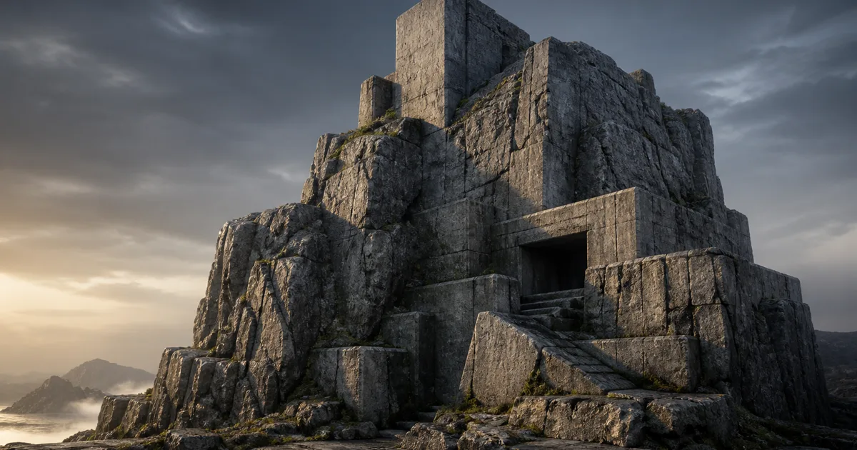
UVs are excellent until the geometry stops cooperating. A sculpted cliff grows another overhang. A procedural cave changes at runtime. A blockout becomes production art through the traditional method of nobody admitting it is still the blockout. The texture then stretches down steep faces, changes scale between pieces, or demands an unwrap that will be obsolete after the next edit.
Triplanar mapping solves that class of problem by projecting a texture from three perpendicular directions and blending the projections according to the surface normal. It can give irregular geometry a stable physical scale without a conventional UV layout. It is not free, and it does not make authored UVs obsolete, but for terrain, rocks, snow, concrete, and generated meshes it is one of the most useful shader tools available.
How triplanar mapping works
A normal texture lookup uses two coordinates, usually U and V. Triplanar texture mapping instead starts with a 3D position in object or world space. The shader builds three 2D coordinate pairs from that position: YZ for the X projection, XZ for Y, and XY for Z. It samples the same texture from all three directions.
The absolute surface normal supplies the blend weights. A face pointing mostly upward favors the Z-axis projection. A vertical face pointing sideways favors X or Y. A diagonal face mixes two or three samples. The weights are normalized so the final contribution adds up to one; raising them to a blend exponent makes the dominant projection sharper.
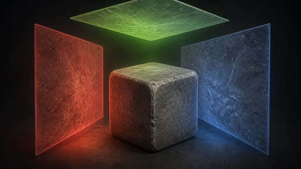
This answers how does triplanar mapping work, but the production details live after the formula. Negative axes may need mirrored coordinates corrected. Object-space position moves with a prop, while world-space position anchors the material to the environment. Normal maps require axis-aware transformation before blending. Scale must use actual scene units or a documented conversion. A basic color-only demo is ten nodes; a trustworthy PBR implementation is a small system.
Triplanar mapping versus UV mapping
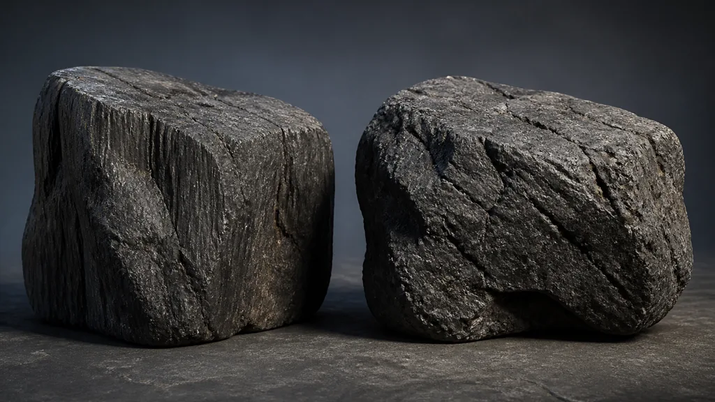
Triplanar mapping without UVs is strongest when the surface is volumetric, irregular, frequently edited, or procedurally generated. It keeps texture density consistent across cliffs, caves, terrain chunks, Boolean architecture, voxel meshes, and rubble. Adjacent objects can share a world aligned texture without artists matching every UV island by hand.
UV mapping remains better when placement matters. Labels, wood boards, masonry bonds, fabric patterns, trim sheets, hero wear, and painted storytelling need deliberate orientation. A three-axis projection does not understand that a door has a front or that every plank grain should follow its length. It merely observes directions with impressive confidence.
Use a hybrid pipeline when appropriate:
- triplanar projection for broad rock, soil, plaster, snow, or concrete;
- UVs for unique painted detail, directional materials, trim sheets, and lightmaps;
- vertex colors or masks for local material placement;
- decals for cracks, leaks, signage, and story-specific wear.
The UV mapping guide explains authored coordinates, while the vertex painting guide covers local masks. These systems are collaborators, not contestants waiting for a dramatic elimination round.
Build a production triplanar shader
Use this sequence to create a reusable triplanar shader rather than a graph that only survives one rock:
- Choose the coordinate space. Use object or local space for movable props and world space for terrain or fixed environment continuity.
- Define physical scale. Convert the position so one texture repeat covers a documented number of metres. Test on known-size geometry.
- Create three coordinate pairs. Use YZ, XZ, and XY for the X, Y, and Z projections, correcting axis signs where mirroring matters.
- Calculate blend weights. Take the absolute geometric normal, apply a controlled exponent, add a small floor if necessary, and normalize the result.
- Sample the PBR maps. Apply identical coordinates and weights to base color, roughness, metalness, AO, height, and normal data where each map exists.
- Reorient normal samples. Transform every projected tangent-space normal into a shared space before blending and renormalizing.
- Add material-scale controls. Expose tile size, projection rotation, offset, blend sharpness, and optional macro variation as instance parameters.
- Validate motion and distance. Rotate, translate, scale, and animate the test mesh; then inspect mips, repetition, and cost on target hardware.
Keep the scale convention visible in the parameter name. TileSizeMeters is useful. TextureScale is a future archaeological site. If artists must remember whether a larger number makes the material larger or tiles it more often, the graph has hidden a decision that belongs in the interface.
Run every map through the same coordinate path. A roughness map projected at a slightly different rotation can create sliding highlights even when base color looks correct. The PBR workflow guide describes the full map contract; triplanar texturing only changes how the shader reaches those maps.
Blend normals without creating projection seams
Base color and scalar maps can be weighted directly. Triplanar normal mapping is harder because each sampled normal begins in the tangent basis of its projection plane. Blending those RGB values as if they shared a coordinate system produces dark seams, inverted relief, and highlights that turn the wrong way near axis transitions.
Unpack each normal, correct its orientation for the corresponding projection, transform it into object or world space, blend using the same axis weights, then normalize. Some engines provide a dedicated triplanar normal mode or a world-aligned normal function. If you build the math yourself, test one unmistakable diagonal groove on each axis before trusting subtle stone noise.
Projection blend sharpness is another tradeoff. A very soft blend hides boundaries but smears features across corners and increases the region where all three samples matter. A sharp blend preserves detail but can expose triplanar texture seams when color, normals, or coordinate signs disagree. Start with a moderate exponent, inspect convex and concave corners, then adjust for the material rather than adopting one studio-wide magic number.
Height-aware blending can make transitions more natural, but it multiplies complexity. Get position, scale, weights, and normals correct first. Shader graphs are fond of advanced features because they cannot feel schedule pressure.
Use slope and height for environmental layers
The normal weights calculated for triplanar mapping can also describe orientation. Upward-facing surfaces can collect snow or dust. Steep faces can expose dry rock. Sheltered transitions can receive moss or dampness. Add world height, cavity, vertex paint, or a broad noise field to stop the result from becoming a perfect altitude diagram.
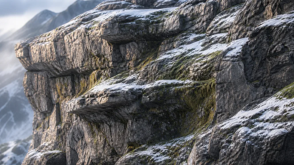
Treat the slope mask as placement, not as the material itself. Snow still needs its own base color, roughness, normal, and possibly height response. Moss should not be green paint over a granite normal. Blend coherent PBR sets and decide whether the top layer fills cavities, sits above relief, or merely changes surface response.
For terrain, combine a quiet tile with a separately scaled macro texture to break repetition. World-aligned coordinates can cross mesh boundaries cleanly, so large landmarks inside the source texture become equally clean repeated evidence. The seamless tileable textures guide covers how to remove both edge seams and internal repetition cues.
Control performance before the sample count multiplies
One triplanar mapping layer samples a texture three times. A PBR set with base color, normal, roughness, AO, and height can therefore require fifteen samples before macro variation, detail normals, or a second material enters the graph. The exact compiled cost depends on engine, platform, packing, derivatives, branching, and what the compiler can share.
Reduce work deliberately:
- pack compatible scalar masks using a documented channel contract;
- skip constant maps instead of sampling a texture filled with one value;
- share coordinates and blend weights across all maps;
- offer a color-only or top-and-side variant for distant geometry;
- sample fewer layers on mobile and VR targets;
- profile the compiled shader rather than counting visible nodes;
- keep ordinary UV materials for assets that already have good UVs.
The texture channel packing guide can turn three scalar lookups into one, subject to compression and color-space constraints. The best triplanar mapping workflow 2026 is not the most elaborate graph. It is the cheapest version that keeps scale, continuity, and lighting correct at the shipped camera distance.
Triplanar mapping in Unity, Unreal Engine, and Blender
For triplanar mapping Unity projects, Shader Graph includes a Triplanar node that samples along the three axes and blends by surface orientation; Unity’s current Shader Graph documentation should match the package version tied to the editor. Keep position, normal, and normal-map spaces explicit. If a generated graph uses world position for a moving object, the object can appear to slide through the texture; switch to object space or transform the coordinates with the object.
For triplanar mapping Unreal Engine, Epic’s WorldAlignedTexture documentation describes world-unit scaling and warns that animated objects can experience texture swimming because the projection stays in world space. Use WorldAlignedNormal for aligned normal data, expose TextureSize as a meaningful parameter, and prefer local-aligned logic for movable props that must carry the material with them.
For triplanar mapping Blender, the Image Texture node documentation provides Box projection and a Blend control. Feed Object or Generated coordinates rather than a flat UV input; Blender’s texture-space documentation notes that Generated coordinates use the object’s texture-space box. Apply or account for object scale so duplicated objects do not mysteriously change texel density.
Across engines, build one test object with top, side, diagonal, concave, and overhanging faces. Animate its translation and rotation. Use a numbered diagnostic grid during development, then remove it from production art. The boring test mesh earns its keep every time a coordinate-space assumption changes.
Diagnose triplanar mapping failures
| Symptom | Likely cause | Fast test |
|---|---|---|
| Texture swims when an object moves | World-space coordinates on a movable mesh | Translate the object while the camera stays fixed |
| Detail changes size between objects | Object scale or texture-space bounds affect coordinates | Apply scale and compare against a one-metre reference |
| Corners become blurry | Blend exponent is too low or three projections overlap broadly | Display axis weights as RGB |
| Hard lines appear at projection boundaries | Weights, signs, or map coordinates disagree | Replace every texture with the same checker |
| Normal detail flips near an axis | Projected normals were not reoriented into one space | Test a strong diagonal normal pattern per axis |
| Pattern is mirrored on one side | Negative-axis coordinates use the wrong sign | Compare positive and negative faces of a cube |
| Material is unexpectedly costly | Too many maps, layers, or repeated calculations | Profile one map, one PBR set, and the final graph separately |
| Large terrain shows obvious repetition | Source tile contains landmarks or lacks macro variation | View a distant overhead render and disable detail normals |
Diagnose color first, then scalar maps, then normals, then multilayer blending. If all systems are enabled during the first test, each artifact gets several plausible alibis.
FAQ
What is triplanar mapping?
Triplanar mapping projects a texture from three perpendicular axes and blends the samples according to the surface normal. It gives irregular meshes consistent texture scale without relying on a conventional UV unwrap.
How does triplanar mapping work?
The shader creates three coordinate pairs from a 3D position, samples along the X, Y, and Z axes, and combines them using weights derived from the absolute surface normal.
Does triplanar mapping need UVs?
No. It can use object-space or world-space position instead of mesh UVs, though UVs may still be needed for lightmaps, unique details, decals, trim sheets, or other material layers.
Is triplanar mapping expensive?
It costs more than a single UV lookup because each texture is usually sampled three times. Packing maps, sharing calculations, reducing layers, and using simpler distant variants can control the cost.
Why does my triplanar texture swim when the object moves?
The shader is probably using world-space position, leaving the projection fixed as the mesh moves. Use object or local coordinates for movable props, or explicitly transform the projection with the object.
Can triplanar mapping use normal maps?
Yes, but the three projected normal samples must be reoriented into a shared coordinate space before they are blended and normalized. Directly mixing their RGB values usually creates incorrect lighting at projection boundaries.
Is triplanar mapping better than UV mapping?
It is better for irregular, procedural, or frequently edited surfaces that need consistent scale. UV mapping is better for exact placement, directional patterns, efficient sampling, and authored control; many production materials use both.
Try CraftPBR
CraftPBR creates the PBR material sets that make triplanar mapping useful across complex geometry:
- Text-to-PBR generates aligned surface maps from a physical material description.
- Photo-to-PBR converts a controlled surface photo into coordinated base color, normal, roughness, height, AO, and metalness.
- Node workspace keeps tiling, map levels, cleanup, and variations editable before shader integration.
- Engine export prepares normal orientation, roughness or smoothness, channel packing, and filenames for common destinations.
- Free tier lets you generate and test a complete material before adding it to a projection shader.
- CC0 output lets you modify, render, and ship generated materials without attribution.
Create a PBR material for your triplanar shader →
Project from three directions. Keep the material decisions pointed in one.