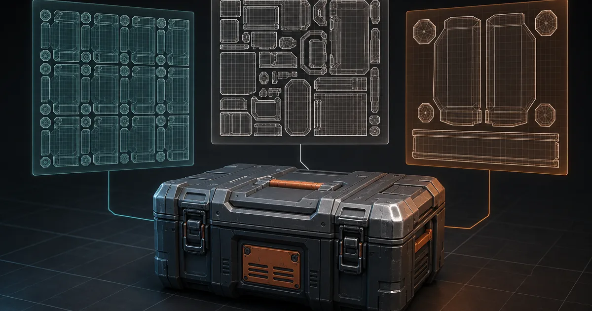
UV channels let one mesh remember more than one way to flatten itself into 2D. The first layout can repeat a tileable steel texture. A second can place a unique dirt mask. Another can reserve non-overlapping space for baked lighting. Geometry stays the same; the address book changes.
The danger is not creating multiple UV channels. That part takes one click. The danger is forgetting which map reads which set after export, LOD generation, shader refactoring, or an engine import preset written by someone who has since escaped into management.
This guide gives each coordinate set a contract, then follows it from Blender to Unity, Unreal Engine, and glTF.
UV channels give one vertex several 2D addresses
A UV coordinate is usually a two-component value attached to a mesh vertex or face corner. A UV channel stores one complete set of those values. Add another channel and the same 3D point receives another 2D address, allowing the same triangle to occupy a different place, scale, or orientation in another texture.
UV sets, map channels, and texture coordinate channels describe the same core idea in different tools. They do not contain pixels and do not duplicate the mesh object. They add vertex attributes that a shader, baker, or lighting system can choose to read.
Each set should solve a coordinate problem, not merely exist because eight slots looked lonely. Common jobs include base PBR textures, unique masks, decals, macro variation, detail tiling, baked lightmaps, and effect data. If two jobs need the same layout, let them share. If their rules conflict, separate them.
UV0 vs UV1 is an index, not a universal promise
The familiar UV0 vs UV1 distinction is zero-based indexing. UV0 means the first set; UV1 means the second. Some DCC tools display names instead, some APIs expose properties such as uv2 for the second set, and some importers reorder channels. The vocabulary is impressively qualified for an array index.
Most pipelines use UV0 for base color, normal, roughness, metalness, AO, and height because those maps form one aligned PBR family. UV1 often becomes the second UV channel for lightmaps or a unique mask. These are conventions, not physics. The material sample and engine setting decide which coordinates are used.
Write the contract beside the asset: index, DCC name, purpose, overlap policy, expected range, and consumers. For example: “UV0 / Material / tileable overlap allowed” and “UV1 / Lightmap / unique 0–1 with padding.” Names help artists; indexes survive into shaders.
A lightmap UV channel needs unique, padded space
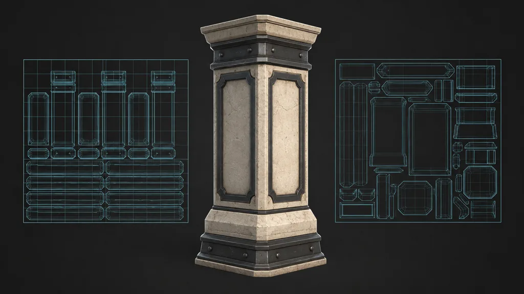
A base material benefits from reuse. Four pillar sides can overlap so each samples the same stone panel at high texel density. A lightmap UV channel has the opposite requirement: each surface needs unique texture space because each receives different baked light and shadow.
Keep lightmap islands inside 0–1, remove overlap, preserve enough spacing for the target lightmap resolution, and avoid thin charts that collapse into a handful of texels. Padding must survive filtering and lower mips; the UV padding guide explains the math behind those borders.
Do not “fix” the base layout by making it obey lightmap rules. You would throw away repeat density to solve another system's constraint. This conflict is exactly why UV channels exist.
Detail maps, masks, and decals need coordinates at their own scale
A detail map UV channel can keep micro detail at a stable tiling rate while the base atlas or unique unwrap handles broad color. A separate set can place a logo-free paint mask, dirt pass, or authored decal without forcing those marks into the repeating texture. Macro variation may use another low-frequency layout when world projection is unsuitable.
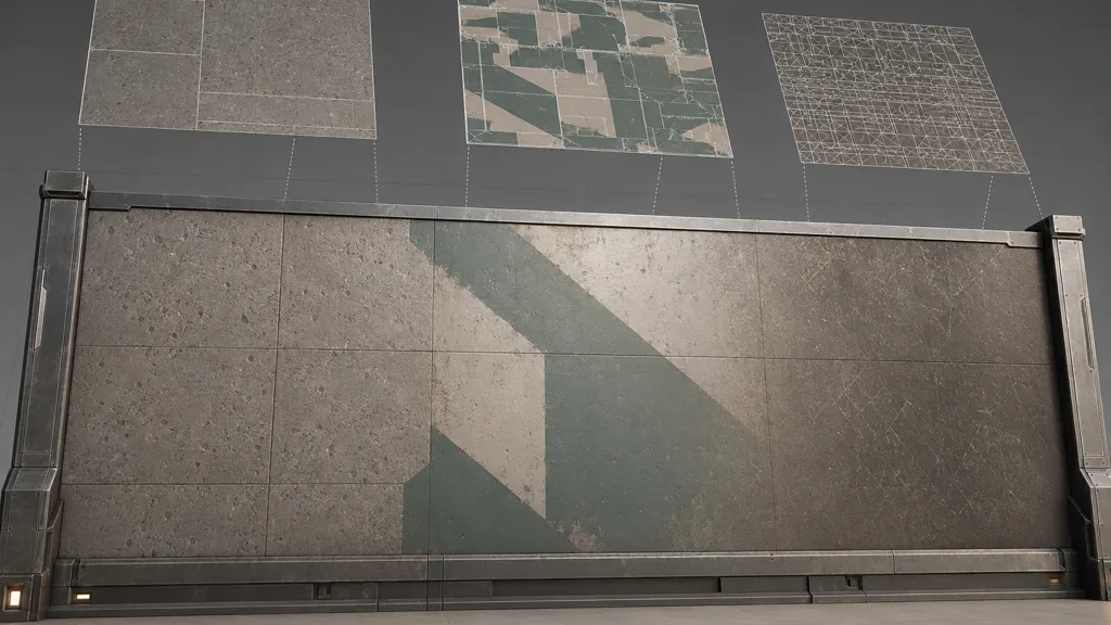
Keep tangent-space normal maps on the coordinate set used for their bake unless the alternate tangent basis is handled deliberately. Moving a normal map to a different unwrap changes seams and tangent directions. Color and scalar masks are more forgiving, but they still need matching layout, padding, wrap mode, and mip behavior.
Before adding a new set, compare alternatives. Object-space or triplanar mapping may solve broad projection. Vertex color may hold a cheap blend mask. A decal component may suit sparse unique marks. Extra coordinates are useful; they are not a loyalty program.
Multiple UV channels add vertex data and pipeline state
Each ordinary 2D set adds two components per rendered vertex. Compression and platform layout vary, but more attributes mean more mesh memory and vertex-fetch bandwidth. UV seams also split render vertices because one geometric point can require different corner values. Add normals, tangents, colors, skinning, and four coordinate sets, and the vertex buffer stops being background paperwork.
The larger cost is often coordination. Bakers need the right set. Materials need explicit sample indexes. Lightmapping needs the intended unique layout. LOD tools must preserve or regenerate every required set. Exporters and runtime formats need compatible limits. A missing channel can make a texture collapse to one color, sample the wrong layout, or appear stretched in ways that encourage innocent people to edit the image.
Measure the final mesh, not only the DCC vertex count. Remove unused UV channels, especially from copied assets and generated LODs. Keep the smallest set of coordinates that passes the material and lighting brief.
Build a UV channel workflow in eight checks
Use this sequence for how to create UV channels that survive production:
- List coordinate jobs. Record repeating textures, unique masks, lightmaps, macro variation, and effect data.
- Keep the base set stable. Let UV0 own the aligned PBR family unless the target contract says otherwise.
- Create only needed sets. Add a channel when two consumers genuinely require incompatible layouts.
- Unwrap by purpose. Permit deliberate overlap for reuse; require unique padded charts for baked lighting.
- Name and order them. Store a readable DCC name plus the exported zero-based index.
- Export a test asset. Inspect the interchange file before sending a whole library through it.
- Bind every consumer. Set texture samples, bakers, and lightmap indexes explicitly.
- Validate the build. Check LODs, seams, padding, stretching, vertex data, and target hardware.
The best UV channel workflow 2026 is dull enough to automate. Reject missing sets, unexpected overlap in the lightmap set, non-consecutive export indexes, zero-area islands, and materials requesting coordinates absent from the mesh.
UV channels in Blender, Unity, Unreal Engine, and glTF
For UV channels Blender, create and name maps in Mesh Data Properties. Blender's UV layout documentation notes that one mesh can store multiple maps, including separate texture and prebaked-lighting layouts. Select the intended active render map, reference named maps explicitly in nodes when needed, and verify which sets the exporter includes.
For UV channels Unity, Unity maps channel 0 to UV0 and TEXCOORD0, channel 1 to UV1 and TEXCOORD1, continuing through channel 7. Its Mesh.SetUVs documentation describes UV0 as the common material set and UV1 as a common baked-lightmap set. Import a known mesh, inspect generated lightmap UV settings, and ensure the shader graph samples the intended channel.
For UV channels Unreal Engine, use Texture Coordinate nodes to select material channels and set the Light Map Coordinate Index on the Static Mesh. Epic's UV channel documentation separates repeating material layouts from unique lightmap layouts. Inspect every LOD in the Static Mesh Editor; channel counts and content can change during reduction or reimport.
The glTF 2.0 specification names sets TEXCOORD_0, TEXCOORD_1, and so on, with consecutive indexes. A texture can select a set through its texCoord property. Verify destination support before assuming every authoring-tool set will round-trip.
Diagnose the channel before repainting the texture
If every sampled pixel looks identical, the mesh may lack the requested set or contain zeroed coordinates. If a unique mask repeats, it is probably reading the tileable set. If baked shadows overlap, inspect lightmap chart uniqueness and coordinate index. If only one LOD breaks, compare its vertex attributes rather than re-authoring all source images.
Use a temporary checker per channel. Give each set a different scale and orientation, then switch the shader sample index one at a time. Inspect the raw UV view in the destination engine. This isolates coordinate failure from color space, compression, normal convention, and the rest of the texture pipeline.
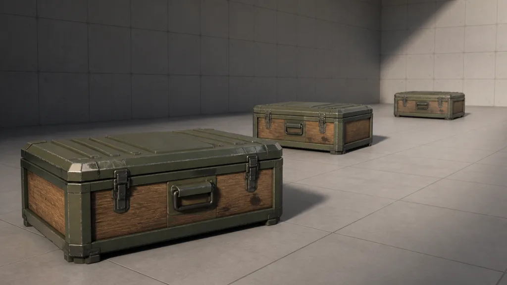
Finish with the real material under fixed lighting. Confirm base maps align, unique marks stay put, detail scale remains stable, lightmaps do not bleed, and lower LODs retain the required UV channels. The PBR material validation guide provides a broader final test.
Try CraftPBR
CraftPBR supplies coherent surface data for the material side of your UV channels contract:
- Text-to-PBR generates aligned base color, normal, roughness, height, AO, and metalness from a material brief.
- Photo-to-PBR turns controlled surface photos into a coordinated map set.
- Node workspace lets you refine maps and masks while keeping their relationships visible.
- Engine export prepares normal orientation, channel packing, color-space intent, and useful filenames.
- Free tier lets you test a complete material and coordinate setup before committing a pipeline.
- CC0 output lets you edit, bake, combine, and ship generated textures without attribution.
Give every texture one map, every coordinate set one job, and every importer a checklist.
Generate a coordinated PBR texture set →