
A microfacet BRDF explains a useful contradiction: rough plaster and polished steel both contain mirror-like reflection, yet one produces a pale blur while the other returns a crisp room. The difference is not whether reflection exists. It is how millions of microscopic surface directions distribute that reflection.
This model sits under most modern physically based shaders. Artists rarely type its equation, but they drive it every time they paint roughness, choose metalness, adjust IOR, or complain that a highlight sparkles like an overcaffeinated disco ball. Understanding the pieces makes those controls predictable.
A microfacet model replaces impossible geometry with statistics
Real surfaces contain scratches, pits, fibers, crystals, machining marks, and grains far smaller than a game mesh or render sample. Modeling them literally would be expensive and often pointless. A microfacet model treats the surface as a statistical field of tiny perfect reflectors instead.
For a particular light direction and view direction, only facets whose normals align with the half vector can reflect that light toward the camera. The half vector is the normalized direction halfway between light and view. A smooth surface has many facet normals crowded near the large-scale surface normal, so their reflections agree and form a tight highlight. A rough surface spreads those normals across more directions, so the same reflected energy occupies a wider lobe.
The common Cook–Torrance form is compact:
f_specular = D × F × G / (4 × N·L × N·V)
The letters are not three mystery knobs. Each answers a physical question:
- D, the normal distribution function: how many microfacets point in the useful half-vector direction?
- F, the Fresnel term: what fraction of light does each suitable facet reflect?
- G, the geometry term: how many suitable facets remain lit and visible instead of being masked or shadowed?
- The denominator: converts between the microscopic facet frame and the projected macroscopic surface.
The PBRT microfacet chapter derives the model and its masking behavior. Disney’s physically based shading notes connect the same theory to artist-facing controls used by principled material models.
D controls highlight shape through the normal distribution function
The normal distribution function, or NDF, says how likely each microfacet orientation is. In current real-time shading, GGX—also called Trowbridge–Reitz—is common because its long highlight tails fit many measured materials and behave more naturally than older, rapidly vanishing lobes.
Roughness changes the width of that distribution. Low roughness concentrates facet normals and produces a narrow highlight. High roughness spreads them, making the highlight broader and less intense. It does not merely blur a finished reflection image. It changes which microscopic orientations contribute before lighting is integrated.
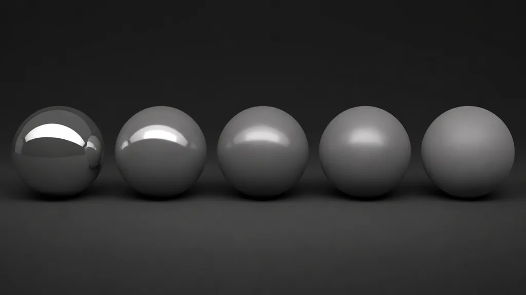
This distinction matters when authoring a roughness map. Paint the physical variation that changes microsurface orientation: polishing, oxidation, fingerprints, dust, worn clear coat, brushed direction, pores, or abrasion. Do not use roughness as a general-purpose brightness control. If a dark patch needs a smaller highlight only because the albedo is dark, the material is lying twice.
Engines may square perceptual roughness before evaluating a GGX BRDF, or expose smoothness as 1 - roughness. That mapping gives artists more useful precision near smooth values. It also means a mid-gray texture is not guaranteed to represent the same internal alpha value in every shader. Export through the target preset and verify with a fixed light rig.
F makes dielectric and metal reflections fundamentally different
The Fresnel term PBR shaders use describes reflectance as the view approaches a grazing angle. Most dielectrics—wood, stone, plastic, ceramic, skin—have modest, nearly colorless face-on reflection and stronger reflection at grazing angles. Their visible base color mostly comes from light that enters, scatters, and exits the material.
Metals behave differently. Their complex index of refraction produces strong, colored specular reflection, while they have effectively no diffuse base layer in the standard metal/rough workflow. Copper reflects warm copper color; gold reflects yellow-orange; silver stays comparatively neutral.

This is why metalness should describe material class, not shininess. Rough metal is still metal. Smooth plastic is still dielectric. Roughness controls lobe width; metalness controls whether base color feeds diffuse response or conductor reflection. The specular map guide covers the alternative specular/gloss workflow, while the index of refraction guide explains dielectric F0 values.
At grazing angles, even a dark dielectric can catch a bright rim. Removing that rim to make rubber look darker usually breaks the material under another camera. Fix the environment, roughness, normal detail, or base response first.
G stops buried facets from reflecting through each other
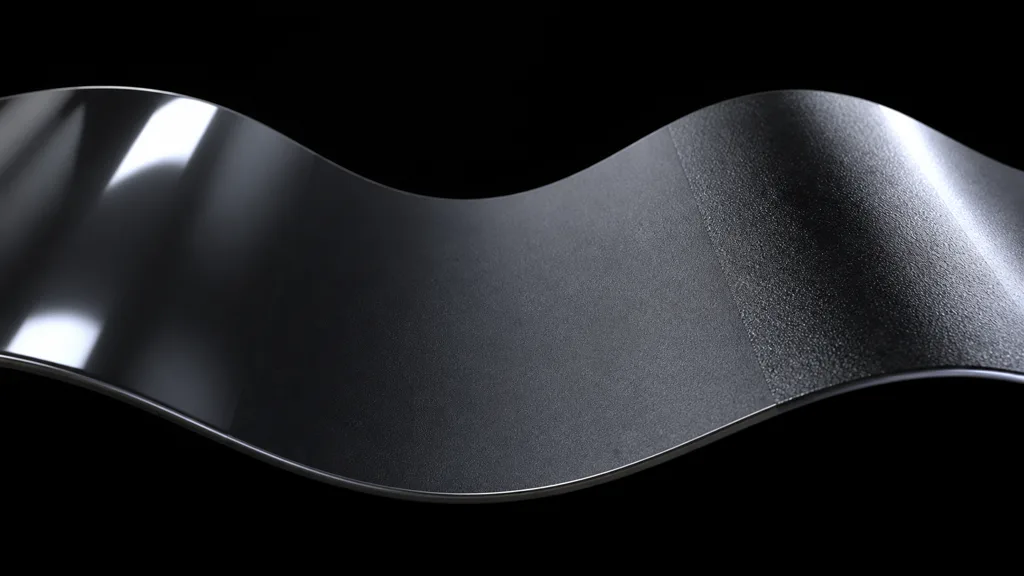
The Smith masking shadowing term accounts for microsurface self-occlusion. A correctly oriented facet may face the light but be shadowed by a neighboring facet. It may reflect toward the camera but sit behind another facet from that view. The geometry term reduces its contribution accordingly.
This effect grows important for rough surfaces and grazing angles. Omitting it makes edges too bright and can violate energy conservation. Common Smith-GGX approximations evaluate masking for light and view directions efficiently enough for real-time use.
Single-scattering microfacet models still lose some energy because they ignore light bouncing between facets. Very rough metals can therefore become darker than real samples. Some offline renderers and advanced real-time models add multiple-scattering compensation. Treat that as part of the shader model, not an excuse to brighten the albedo until one preview sphere looks cheerful.
Normal maps complicate G because the shading normal may diverge sharply from the geometric normal. Extreme normal strength can reflect energy from impossible directions, expose terminator artifacts, and create glitter at distance. Keep authored normals plausible, preserve tangent space, and use geometric or specular anti-aliasing when tiny variations collapse below a pixel.
Microfacet BRDF roughness is a signal, not decorative grayscale
A useful microfacet BRDF roughness texture records variation in the statistical slope distribution. Work in linear data space. Do not apply sRGB decoding to roughness, metalness, AO, or packed masks. The sRGB versus linear textures guide explains the import boundary.
Build a dependable roughness signal in this order:
- Define the base material class and a believable average roughness.
- Add broad process variation: polish zones, weather exposure, handling, coating thickness, or moisture.
- Add mid-scale evidence tied to actual surface events such as scratches, pores, fingerprints, dust, and oxidation.
- Add only microdetail that survives the target resolution and mip chain.
- Preview under one small bright source, one broad source, and a neutral HDR environment.
- Check motion at gameplay distance, not only a still close-up.
Roughness needs coordinated evidence. A deep scratch may change normal, height, base color, and roughness together. Dust may raise roughness while softening normal detail. Generated or scanned maps should remain aligned; random noise copied independently into every channel creates a material assembled by committee, and none of the committee attended the same meeting.
Stop specular aliasing before it becomes a post-process problem
Specular aliasing on rough materials often starts with detail that is locally too smooth, too strong, or too small for the pixel footprint. A bright light hits a few surviving normal samples, producing fireflies or crawling highlights. Temporal anti-aliasing can hide some symptoms, but unstable material input remains unstable.
Use several defenses together:
- filter normal variance into higher roughness as detail enters smaller mips;
- reduce implausibly strong high-frequency normal slopes;
- preserve roughness mips instead of letting compression flatten them unpredictably;
- enable engine specular AA or geometric anti-aliasing where available;
- test compressed target formats, especially when roughness shares a packed texture;
- avoid exact zero roughness unless the asset and renderer genuinely need it.
Do not solve every sparkle by clamping direct light. That also erases legitimate highlights from clean surfaces. Inspect the roughness mip, normal mip, light angular size, and BRDF settings separately. The texture filtering guide helps isolate footprint and mip failures.
Microfacet BRDF in Unity, Unreal Engine, and Blender
For a microfacet BRDF Unity material, Standard, URP Lit, and HDRP Lit expose variants of metallic or specular workflows while hiding most DFG math. Confirm whether the pipeline wants smoothness or roughness, which channel stores it, and whether specular AA is available. Custom Shader Graph code should reuse the pipeline’s lighting functions when possible; a hand-copied GGX term can disagree with image-based lighting, clear coat, fog, or shadowing.
For a microfacet BRDF Unreal Engine material, the default lit model already maps base color, metallic, specular, roughness, and normal into the engine BRDF. Keep most dielectrics near the default specular value unless measured IOR demands a change. Use material functions for authored transformations, but avoid rebuilding the entire BRDF merely to make one asset brighter.
For a microfacet BRDF Blender setup, Principled BSDF exposes metallic, roughness, IOR, coat, anisotropy, and other lobes on one model. Blender’s Principled BSDF manual defines roughness as microfacet roughness and metallic as the dielectric-to-metal model blend. Match export conventions rather than copying node numbers blindly into a game engine.
Across engines, validate the same reference spheres, maps, exposure, environment, and normal orientation. Differences can come from roughness remapping, environment prefiltering, BRDF lookup tables, multiple scattering, tone mapping, or light size. “PBR” narrows the disagreement; it does not make every renderer identical.
FAQ
What is a microfacet BRDF?
A microfacet BRDF models a surface as a statistical collection of tiny mirror-like facets. It combines their orientation distribution, Fresnel reflectance, and masking-shadowing to predict how much light reflects from one direction into another.
How does a microfacet BRDF work?
It finds the half vector between the light and view, evaluates how many facets align with it, how strongly those facets reflect, and how many remain visible and illuminated. The common Cook–Torrance form combines those answers as D, F, and G terms.
What is GGX in PBR?
GGX is a widely used microfacet normal distribution, also called Trowbridge–Reitz. Its long tails produce plausible highlight behavior across smooth and rough materials and work well with efficient Smith masking approximations.
Does roughness reduce reflection?
Roughness mainly spreads reflection across a wider set of directions, making highlights broader and dimmer at any one pixel. Masking, multiple scattering, environment filtering, and the renderer’s energy compensation also affect final brightness.
What are D, F, and G in a BRDF?
D is the microfacet normal distribution, F is Fresnel reflectance, and G is geometric masking-shadowing. Together they describe facet availability, per-facet reflection, and visibility.
Why do rough materials sparkle in motion?
Their normal or roughness detail may be smaller than a pixel, undersampled, or damaged by mip generation and compression. Filter normal variance into roughness, use specular anti-aliasing, and inspect target mips under a bright moving light.
Is a normal map part of the microfacet BRDF?
A normal map changes the shading frame used to evaluate the BRDF, while roughness describes the unresolved distribution below that frame. They represent different scales and should not be used as interchangeable detail controls.
Try CraftPBR
CraftPBR creates the coordinated inputs a microfacet BRDF needs:
- Text-to-PBR generates aligned base color, normal, roughness, height, AO, and metalness from a material description.
- Photo-to-PBR turns a controlled surface reference into editable material maps instead of preserving baked lighting.
- Node workspace keeps roughness ranges, normal strength, tiling, levels, and masks adjustable together.
- Engine export prepares normal orientation, linear scalar data, channel packing, filenames, and target conventions.
- Free tier lets you generate and validate a full material before committing it to production.
- CC0 output lets you modify, combine, bake, render, and ship generated textures without attribution.
Build the maps behind the equation
Generate a coherent PBR set, then test its roughness and normal detail under your destination shader.
Build a material in CraftPBRThe equation is compact. The surfaces it explains are not.