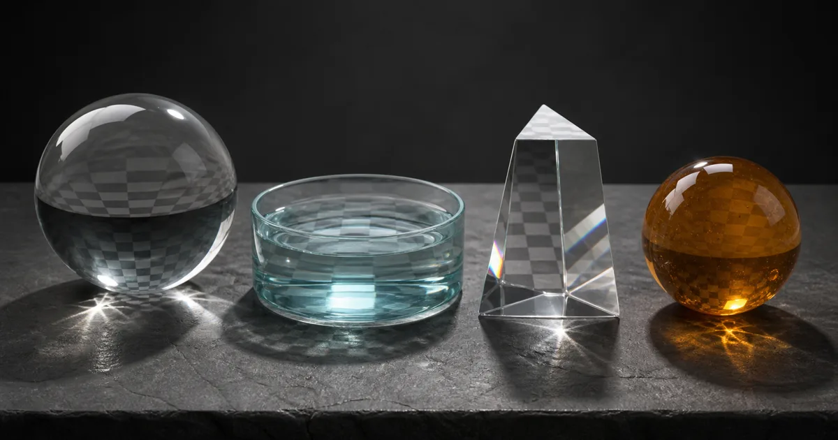
Set every transparent shader to 1.5 and the render may look acceptable. Set every opaque dielectric to its default specular value and it may also look acceptable. This is how index of refraction in 3D becomes a drawer where physically meaningful numbers go to lose their labels.
IOR is not a generic realism control. It describes the ratio between the speed of light in two media, and renderers use that relationship to decide how light bends at an interface and how much reflects there. Water, acrylic, window glass, resin, ice, and diamond should not inherit one “glass-ish” preset merely because they can all be shiny.
This guide connects the number to visible evidence. You will separate refraction from Fresnel reflection, translate IOR in PBR between renderers, avoid values that disguise geometry problems, and build a test scene that can expose an incorrect material before a cinematic camera politely hides it.
Index of refraction in 3D controls two different cues
The PBR index of refraction is usually written as n or eta. Vacuum is 1.0, air at sea level is very close to 1.0, water is roughly 1.333, common glass sits around 1.5 to 1.6, and diamond is about 2.42. The exact value varies with composition, wavelength, temperature, and sometimes pressure, but those averages are useful for ordinary rendering.
At a dielectric boundary, IOR affects two linked results:
- Direction. Snell’s law determines how a transmitted ray bends. Entering a higher-IOR medium from air bends the ray toward the surface normal; leaving it bends the ray away.
- Energy split. The Fresnel equations determine what fraction reflects and what fraction transmits. Even perfectly clear glass reflects some light, and the reflected fraction rises toward grazing angles.
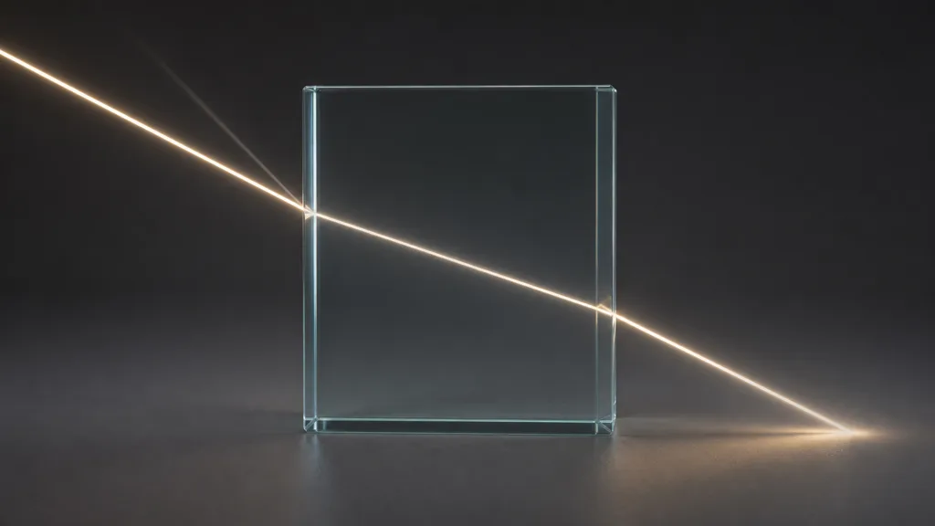
These cues can appear separately in real-time tools. An opaque plastic cannot show background refraction, yet its dielectric specular response still follows an IOR-derived Fresnel term. A screen-space glass shader may distort the scene but approximate thickness, internal reflections, or objects outside the screen. When the renderer exposes two controls, do not assume they represent two independent physical properties.
Relative IOR matters more than the isolated number
Light responds to the ratio between the IOR on each side of an interface. A glass object with IOR 1.5 in air has a strong boundary. The same glass submerged in a liquid with a similar IOR can nearly disappear because the ratio approaches one. That is why a transparent bead can become hard to see in index-matching fluid without becoming less solid.
Most material interfaces assume the outside medium is air. That is a sensible default for a bottle on a table and the wrong model for a bubble under water, liquid inside glass, or nested optical parts. A physically capable path tracer needs boundaries and normals that communicate which medium a ray is entering or leaving. A real-time approximation may offer only a single surface distortion, so document the compromise instead of compensating with a fictional value.
Geometry is part of the optical model. A solid glass object needs thickness and a closed, consistently oriented mesh. A thin window may need a dedicated thin-surface shader that avoids pretending the pane contains a large refractive volume. Duplicate faces, flipped normals, zero-thickness shells, and overlapping boundaries can all make a correct IOR look wrong. The slider is often innocent; it just has poor legal representation.
Read IOR values for materials without turning them into presets
Use measured values as starting constraints, then match the actual substance and renderer. These practical ranges are averages, not certificates of composition.
| Material | Useful starting IOR | What should also change |
|---|---|---|
| Air | 1.0003 | Usually treated as 1.0 by renderers |
| Ice | 1.31 | Roughness, bubbles, cracks, volume absorption |
| Water | 1.333 | Surface normal scale, depth, absorption, reflection environment |
| Acrylic / PMMA | About 1.49 | Edge polish, tint, scratches, thickness |
| Common glass | About 1.50–1.60 | Roughness, absorption, inclusions, thickness |
| Crystal / high-index glass | About 1.6–1.9 | Dispersion when supported, cut geometry, absorption |
| Diamond | About 2.42 | Faceting, dispersion, internal paths, extreme cleanliness |
Searches for IOR values for materials often produce tables with more decimal places than an art pipeline can justify. Before copying one, check wavelength, material formulation, and whether the value describes a solid, a coating, or a solution. “Plastic” is not one substance. Neither is “glass.”
Do not raise IOR to make a weak reflection brighter before checking the environment. A black glass object in a black world has nothing useful to reflect. Do not lower IOR to hide overactive refraction before checking thickness and normals. Physical numbers work best after the scene supplies physical evidence.
Convert dielectric F0 from IOR without guessing
For a smooth dielectric viewed head-on from air, the base Fresnel reflectance is commonly written:
F0 = ((IOR - 1) / (IOR + 1))²
An IOR of 1.5 gives an F0 of 0.04, or four percent. Water at 1.333 gives roughly two percent. IOR 2.42 gives about seventeen percent. At grazing angles, reflection rises toward one regardless of that face-on value, which is why clear materials acquire strong silhouettes.
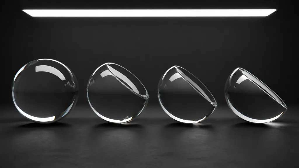
This dielectric F0 from IOR conversion explains why some engines expose specular, specular IOR level, or F0 instead of a direct IOR for opaque surfaces. Confirm the mapping before entering 1.5 into a field that expects a normalized artistic weight. A familiar number in the wrong coordinate system remains wrong, only confidently.
Metallic materials are different. Conductors use wavelength-dependent complex IOR values, including an absorption component, and the metal/roughness workflow normally represents their colored reflection through base color plus metalness. Do not use a dielectric IOR slider to tune copper, gold, or aluminum.
How to set IOR in a 3D material
- Name the substance and its context. Record glass type, liquid, resin, ice, or coating, plus the medium outside it.
- Fix the geometry. Use closed thickness for volumes, consistent normals, and a thin-surface model only for genuinely thin sheets.
- Start with a measured IOR. Choose a defensible value or range; avoid tuning under dramatic lighting.
- Separate surface and volume controls. Set roughness and normals at the boundary, then absorption, scattering, or tint through the thickness.
- Check face-on reflection. Compare the dielectric response under a broad white source before enabling refraction.
- Check grazing reflection. Rotate the camera and object; the edge response should grow without becoming a painted white rim.
- Enable transmission or refraction. Place a checker or straight-edged object behind the material so distortion is measurable.
- Test thickness. Compare a thin pane, sphere, and thick block. Absorption should increase with path length, while IOR itself should stay constant.
- Profile the shipped path. Verify sorting, screen-space limits, ray-tracing quality, fallback shaders, and target hardware.
The best IOR workflow 2026 stores the physical value beside the asset and records renderer-specific translations separately. That lets a glass preset move between tools without pretending their transparency algorithms are identical.
Translate IOR in Unity, Unreal Engine, and Blender
For IOR Unity, HDRP Lit can expose refraction when the surface is transparent and refraction is enabled in the material and pipeline. Choose an appropriate refraction model, then set thickness, transmittance, and index of refraction together. URP’s standard Lit shader does not offer the same full volumetric glass model, so Shader Graph or a custom solution often approximates scene distortion. Unity’s HDRP Lit documentation is the useful reference for the actual package version in the project.
For IOR Unreal Engine, a translucent material can use the Refraction input with an Index of Refraction mode. Epic’s refraction guide lists common values and shows the material setup. Epic also documents Pixel Normal Offset as an alternative for large flat surfaces such as water, where physical screen-space IOR can read beyond available scene color. Decide whether the material represents a small volume or a broad distortion surface before selecting the mode.
For IOR Blender, Principled BSDF exposes IOR and Transmission Weight, with Roughness, Coat, and volume nodes handling different parts of the result. Build solid glass with real thickness, use a volume absorption node when color should increase with depth, and verify the render engine’s transmission settings. Blender’s Principled BSDF manual defines the inputs; the renderer and version determine which paths are available in Eevee and Cycles.
Translate intent rather than screenshots: interface ratio, face-on reflectance, grazing response, roughness, thickness, and absorption. A viewport that omits internal paths cannot be forced into path-traced accuracy by adding decimals to IOR.
Diagnose index of refraction failures by what stays wrong
| Symptom | Likely cause | First useful test |
|---|---|---|
| Glass is invisible | No reflection environment, IOR ratio near one, or opacity setup wrong | Add one broad light and a checker backdrop |
| Object looks like chrome | Transmission disabled or roughness/specular mapping wrong | Disable metalness and inspect the shader model |
| Refraction swims with the camera | Screen-space sampling or unstable normals | Lock the object and move the camera slowly |
| Thin pane bends the scene too much | Solid-volume model on zero-thickness geometry | Switch to a thin-surface model or add thickness |
| Thick amber block has uniform color | Tint is on the surface instead of volume absorption | Compare thin and thick meshes at one exposure |
| Silhouette is a white outline | Fresnel added without energy sharing or clipped lighting | Test middle-gray glass under a broad source |
| Water looks like a glass brick | Thickness, normals, and refraction mode ignore scale | Use a shallow plane and inspect wave amplitude |
| Nested glass flickers or turns black | Overlapping boundaries, flipped normals, or depth limit | Separate shells and inspect normal orientation |
When asking how does IOR affect reflections, isolate the reflection first. When asking what IOR should glass use, identify the glass and render context first. Both questions become harder when opacity, roughness, absorption, normals, and post-processing move at the same time.
Validate index of refraction in 3D with a small optical rig
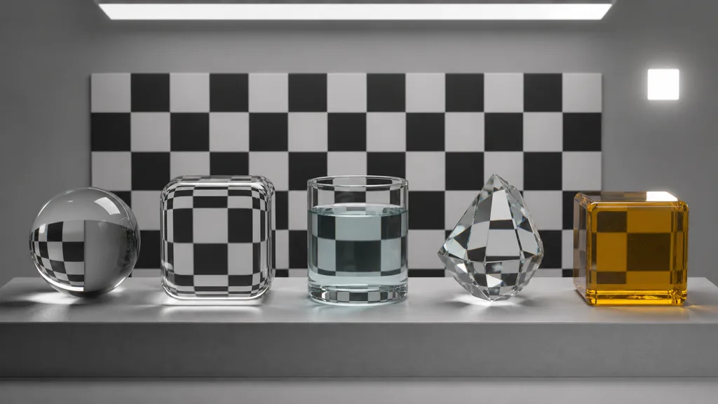
Build one reusable scene with a sphere, thick rounded block, thin pane, liquid vessel, and production mesh. Put a black-and-white checker behind them, add one broad strip light plus one small source, and keep exposure fixed. The checker reveals distortion; the lights reveal Fresnel width and roughness; multiple thicknesses reveal whether tint belongs to the surface or the volume.
Render from face-on and grazing angles. Then move the camera so screen-space refraction must sample near the frame edge. Test opaque dielectric reflection separately from transmission, and compare raster, ray-traced, and offline paths when the project uses more than one. The sRGB vs linear textures guide covers scalar-map import, while the clear coat materials guide explains what changes when another dielectric boundary sits above the base.
Finally, inspect the asset in motion and on target hardware. Sort transparent surfaces, watch temporal noise, test reflection fallbacks, and measure cost. Correct index of refraction in 3D is a foundation, not an exemption from the renderer’s limitations.
FAQ
What is index of refraction in 3D rendering?
Index of refraction is the ratio describing how quickly light travels in one medium relative to another. A renderer uses relative IOR to compute transmitted direction through Snell's law and reflected energy through the Fresnel equations.
What IOR should glass use?
Common glass usually starts around 1.5 to 1.6, but composition matters. Use about 1.52 for ordinary glass when no better measurement exists, then tune roughness, thickness, absorption, and geometry instead of moving IOR to solve unrelated problems.
Does IOR affect opaque materials?
Yes. Opaque dielectrics still reflect light at their surface, and many PBR shaders derive their face-on specular reflectance from IOR. They simply do not show a transmitted background path.
Is IOR the same as roughness?
No. IOR controls the interface's Fresnel response and refraction, while roughness spreads reflection and transmission across microfacet directions. Rough and polished glass can share the same IOR.
Why does my glass look metallic?
Metalness may be enabled, transmission may be missing, or the material may have nothing useful behind it. Restore a dielectric shader, add a readable environment and backdrop, then verify opacity and refraction settings.
Can I texture index of refraction?
Only when the surface genuinely contains different substances or an intentional approximation requires it. Most wear belongs in roughness, normals, thickness, absorption, or a material mask; noisy IOR variation is rarely the physical cause.
Why does refraction look different between Blender, Unity, and Unreal?
They may use different path-traced, ray-traced, screen-space, or distortion approximations and different thickness assumptions. Match the physical value and visible intent, then document the engine-specific model and its limits.
Try CraftPBR
CraftPBR creates the coordinated surface maps that make index of refraction in 3D readable while the destination renderer handles the optical boundary:
- Text-to-PBR generates a complete material set from a description of substance, surface finish, scale, wear, and color.
- Photo-to-PBR converts a controlled reference into aligned base color, normal, roughness, height, AO, and metalness maps.
- Node workspace keeps roughness, normal detail, masks, levels, tiling, and material variants editable.
- Engine export prepares normal orientation, linear masks, channel packing, filenames, and target-specific conventions.
- Free tier lets you generate and test a full surface set before tuning transmission or renderer-specific IOR controls.
- CC0 output lets you modify, render, and ship generated textures without attribution.
Give the number a substance, an interface, and a test scene. It has been freelancing as a shine slider for long enough.