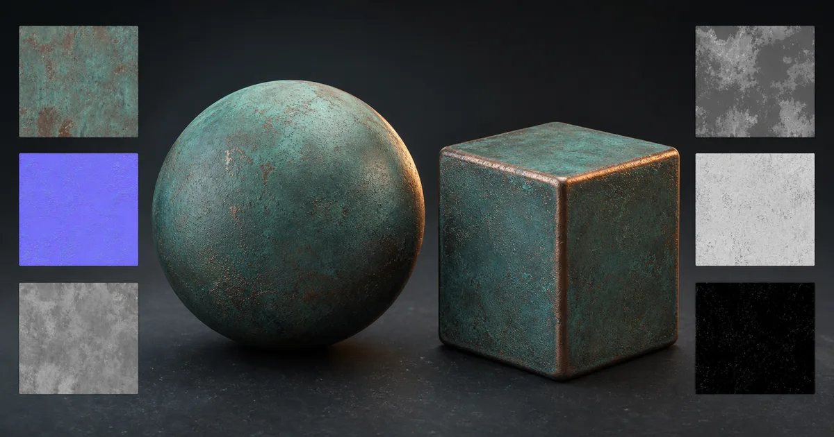
Blender opens a new material with Principled BSDF already waiting. That convenient orange node is the centre of a good Blender PBR materials workflow, but it cannot identify which image is colour, which is data, whether a normal map points the right way, or how many millimetres a height value represents. Those decisions still belong to the person connecting the cables.
This guide builds one material from a standard map set, then explains colour spaces, normals, displacement, packed channels, scale, and validation in both Cycles and EEVEE. The goal is not an impressive node screenshot. It is a reusable material that keeps its story straight when the light, mesh, camera, or render engine changes.
Build Blender PBR materials in this order
Start with the plainest possible shader. Add complexity only after the surface works under neutral light.
- Create a material and keep the default Principled BSDF connected to Material Output.
- Add one Image Texture node per source map, or one node for each packed texture.
- Connect base colour to Base Color and leave its image colour space as sRGB when the file was authored for display.
- Mark roughness, metalness, normal, height, ambient occlusion, and packed masks as Non-Color data.
- Connect roughness directly to Roughness and metalness directly to Metallic.
- Pass a tangent-space normal map through a Normal Map node before connecting it to Normal.
- Send height through a Bump node for shading relief or a Displacement node for geometric relief.
- Test the material on simple geometry before adding mixing, dirt, edge wear, or procedural variation.
This order matters because each stage answers a different question. Base colour describes pigment. Roughness describes reflection spread. Metalness classifies the exposed substance. Normal and height describe surface direction or elevation. Ambient occlusion can add restrained cavity influence, but it is not a substitute for the renderer’s lighting.
A clean Blender PBR material setup should remain readable at a glance. Frames, reroutes, and consistent node placement help when the material grows. Forty decorative reroutes do not make the shader more accurate, but they do give the noodles a formal education.
Wire the Principled BSDF by physical meaning
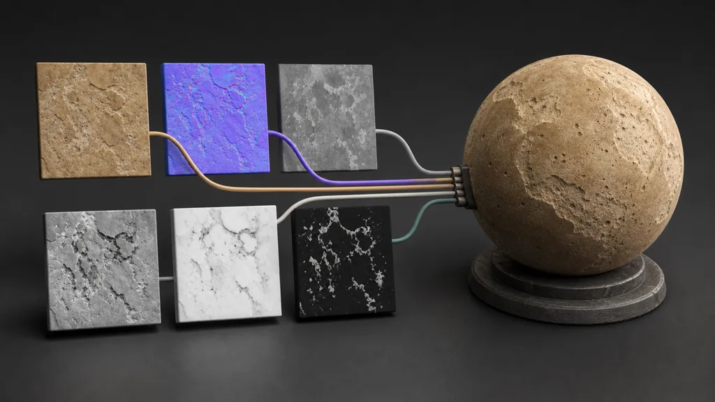
The modern Principled BSDF combines common surface layers in one shader. For ordinary opaque Blender PBR materials, the core connections are straightforward:
- Base Color: lighting-neutral colour or albedo. It should not contain a fixed highlight, cast shadow, or heavy cavity shading.
- Roughness: black values produce sharper reflections; white values spread them. Connect roughness, not smoothness. If the source provides gloss or smoothness, invert it once and document the conversion.
- Metallic: use values near 0 for dielectric substances such as stone, wood, paint, rust, and plastic, and near 1 for exposed metal. Dirt or paint over metal remains dielectric at the coated pixels.
- Normal: feed a tangent normal through a Normal Map node. Do not connect the purple RGB image directly to the shader’s vector socket.
- Height: use Bump for inexpensive microrelief or Displacement for geometry changes. One grayscale file can drive either route, but the scale and quality requirements differ.
- Ambient Occlusion: Principled BSDF has no universal “make this PBR” AO socket. Multiply subtle AO into base colour only when the target look and lighting pipeline require it, or keep it available for controlled mixing.
For a reusable Blender Principled BSDF texture setup, expose a small set of controls: UV scale, roughness range, normal strength, displacement scale, and perhaps tint. Preserve the source maps underneath those controls.
Set colour spaces before adjusting values
Colour management is the most common invisible error in Blender PBR materials. Base colour usually contains display-referred colour, so Blender converts it into the scene-linear working space. Roughness, metalness, normals, height, AO, and masks contain numbers rather than visible colour. Set those Image Texture nodes to Non-Color so Blender does not apply a colour transform to the data.
- sRGB or the source’s authored colour space: base colour, emissive colour, and other genuinely coloured imagery.
- Non-Color: roughness, gloss, metalness, normal, bump, displacement, AO, opacity masks, and channel-packed data.
- Linear or scene-linear formats: use the file’s actual encoding for EXR or a managed studio pipeline; do not relabel a file merely because the menu offers many choices.
An incorrect Blender roughness map setup often looks plausible in one light and wrong everywhere else. When roughness is mistakenly treated as sRGB, mid-range values are transformed before shading. The surface may become too glossy, too flat, or oddly contrasty. Blender will render it without complaint. It assumes you have a reason, which is generous.
The same problem damages packed masks. A single RGB image may carry three independent scalar channels, none of which are colour. Mark the whole image Non-Color before separating those channels.
Make normals and displacement do different jobs
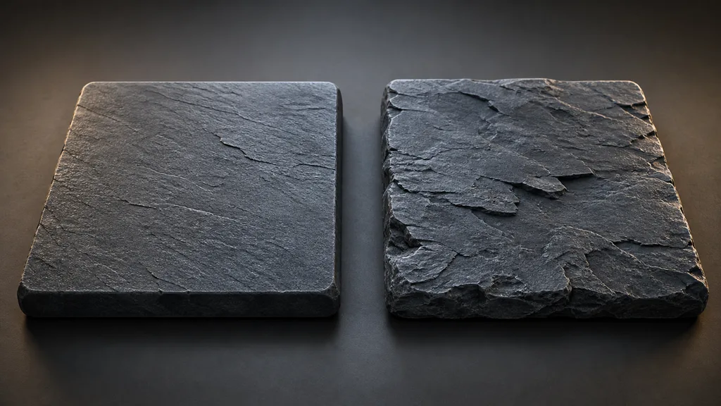
In Blender PBR materials, normal, bump, and displacement are related, not interchangeable.
A tangent normal map changes the shading normal while leaving the mesh silhouette intact. In a Blender normal map setup, mark the texture Non-Color, connect its Color output to a Normal Map node, keep the node in Tangent space for the common workflow, and connect the result to Principled BSDF Normal. The normal map must use the same UV set as the surface textures.
Blender commonly works with OpenGL-style tangent normals. If a DirectX map makes dents look raised and ridges look recessed, invert the green channel during export or with a controlled node operation. Do not guess from the purple thumbnail; rotate a hard light across a known raised detail.
A grayscale bump map goes through a Bump node. It changes shading but not geometry, which makes it useful for pores, scratches, weave, and other fine detail. Keep strength restrained.
For a Blender displacement map setup, feed a Non-Color height map into a Displacement node, define its midpoint and physical scale, then connect it to Material Output’s Displacement input. True displacement needs sufficient mesh subdivision and the appropriate material and render settings. Render-engine support can vary by Blender release, so verify the final scene in the engine and version that will produce the frames.
Use true displacement for silhouette-changing forms such as deep mortar, torn bark, layered rock, or large cracks. Use normal or bump for fine detail. Combining broad displacement with micro normal detail usually gives a better cost-to-result ratio.
Unpack ORM and other channel-packed textures
Game-ready Blender PBR materials often arrive with several grayscale maps stored in one RGB texture. ORM usually means ambient occlusion in red, roughness in green, and metalness in blue, but verify the export preset before wiring it.
- Load the packed image into one Image Texture node.
- Set it to Non-Color.
- Add a Separate Color node in RGB mode.
- Connect the documented channel to its destination: roughness to Roughness, metalness to Metallic, and AO to any deliberate AO treatment.
- Leave unused channels disconnected rather than inventing a purpose for them.
Unity exports may pack metallic and smoothness differently. Unreal projects often use ORM. glTF commonly uses a metallic-roughness texture whose green channel stores roughness and blue stores metalness, while occlusion may be delivered separately. The filename is evidence, not a sworn statement.
Keep separate lossless masters when authoring Blender texture maps. Packing is a delivery optimization. If maps need different resolution, UVs, interpolation, wrapping, or bit depth, forcing them into one texture can create more problems than it solves.
Control UV scale, tiling, and projection
Technically correct Blender PBR materials can still look false because their bricks are the size of doors. Record the physical coverage of every tile and preserve it when adjusting UVs.
For conventional UV mapping, connect Texture Coordinate to Mapping, then feed the Mapping vector into every related Image Texture. One shared vector path keeps the maps registered. Apply object scale when modifiers, generated coordinates, or displacement depend on it, and inspect texel density rather than typing the same mapping value into every object.
Test a tile over at least a four-by-four area. Matching opposite edges removes seams, but a bright stone, dark stain, or large crack can still reveal the repeat. Add macro variation separately with a low-frequency procedural mask, object colour, decals, or a second texture.
Box or triplanar projection helps rocks and terrain where UV seams are awkward, though directional patterns such as wood grain and brick courses require more control. Unique hero assets may use baked UV maps instead.
Diagnose the material one symptom at a time
When Blender PBR materials look wrong, disconnect maps instead of adjusting everything simultaneously.
- The surface looks wet: roughness may be inverted, marked as sRGB, too dark, or crushed by a ramp.
- Relief is inside out: the tangent normal likely uses the wrong green-channel convention, or the Bump node has the wrong direction.
- Paint looks metallic: the metalness map classifies brightness instead of substance, or a packed channel is connected incorrectly.
- Colour contains a fixed shadow: base colour still includes captured lighting or multiplied AO.
- Displacement barely appears: the mesh lacks subdivision, material settings use bump only, scale is too low, or the height midpoint is wrong.
- Displacement explodes: object scale, height units, midpoint, or map range is inconsistent.
- The material sparkles at distance: micro-normal or roughness contrast exceeds what the mip resolution can support.
- Every map is offset differently: image nodes do not share the same coordinates, UV map, or mapping transform.
- A packed texture behaves strangely: the image is not Non-Color, channel order is wrong, or compression has damaged mask values.
Replace base colour with neutral grey to judge roughness and relief. Then disconnect normal and height to inspect base colour alone. Rotate one small area light and watch the highlight, because material errors are often easier to see in motion.
The roughness map guide, normal map guide, displacement map guide, and texture resolution guide cover those components in more depth.
Validate Blender PBR materials in a small material lab
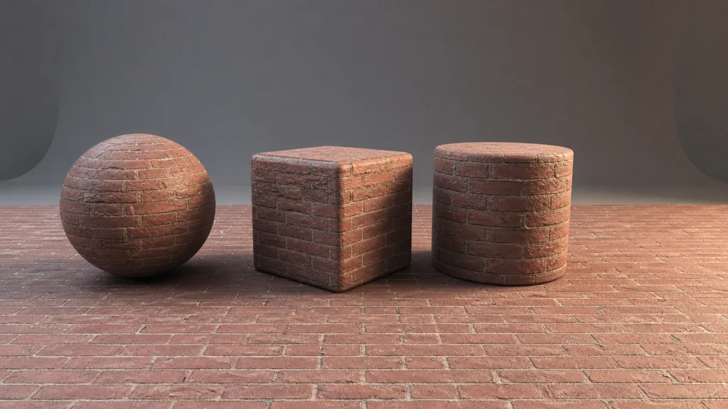
To review Blender PBR materials, build one reusable .blend file with a UV sphere, beveled cube, cylinder, large plane, real-scale reference, neutral world light, and one movable area light.
- Rotate the area light across the sphere to inspect roughness range and normal orientation.
- Use the beveled cube to expose UV seams, tangent discontinuities, and implausible edge behaviour.
- Use the cylinder to reveal directional stretching and projection problems.
- Tile the plane repeatedly and inspect it from close, middle, and distant cameras.
- Switch between Cycles and EEVEE if the asset must support both, then render the target engine.
- Inspect memory, resolution, and shader complexity at the intended shot or gameplay distance.
- Save the approved node group with physical scale, map convention, normal orientation, and source notes.
The best PBR materials for Blender 2026 are not defined by node count. They are predictable under different lights, use correct data transforms, keep map features aligned, and can be handed to another artist without a guided tour of unnamed ramps.
Try CraftPBR
CraftPBR turns material creation into an editable route for Blender PBR materials:
- Text-to-PBR creates a coordinated map set from a physical material description.
- Photo-to-PBR converts a captured surface into aligned base colour, normal, roughness, height, AO, and metalness.
- Node workspace keeps masks, tiling, range corrections, and material layers adjustable.
- Engine export prepares OpenGL normals, correct map names, colour and data conventions, and Blender-ready delivery.
- Free tier lets you test a real material before committing to a production workflow.
- CC0 output lets you use, modify, and ship generated materials without attribution.
Create Blender-ready PBR materials with CraftPBR →
Build the shader so the next person can understand it before the coffee gets cold.