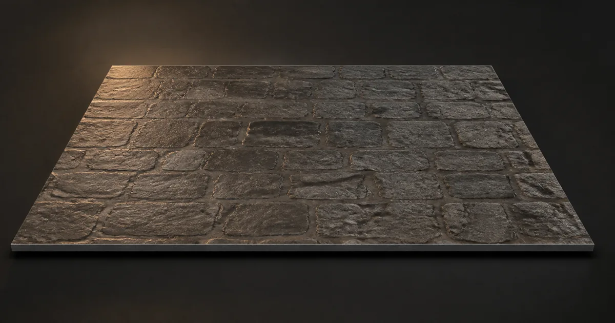
Parallax occlusion mapping makes a flat polygon appear to contain deep cracks, raised bricks, recessed mortar, or carved panels. Instead of moving vertices, the shader follows the camera’s view direction through a height map and finds the part of the virtual surface that should be visible. The resolved coordinates then drive the material textures.
This sits between a normal map and true displacement. A normal map changes how light reacts but cannot hide one texel behind another. Displacement changes geometry and can alter the silhouette, shadows, and collision, but needs enough mesh detail and processing. A POM shader spends pixel work to create stronger depth while leaving the mesh untouched.
That compromise is useful for brick, stone, cobbles, carved plaster, damaged concrete, roof tiles, and other surfaces with meaningful inset relief. It is less useful for fuzzy materials, thin cutouts, distant surfaces, or anything whose outer profile tells the story.
How parallax occlusion mapping finds a surface
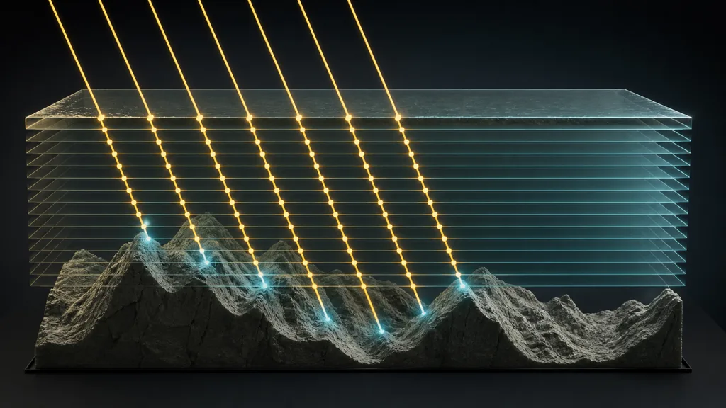
To answer how does parallax occlusion mapping work, imagine a ray entering a shallow box above the texture. The shader transforms the view direction into tangent space, divides the virtual depth into layers, and advances the texture coordinates one step at a time. At every step it compares the ray depth with the sampled height.
When the ray crosses the stored surface, the search has bracketed an intersection. Interpolating between the final two samples reduces obvious stair steps. More advanced versions use a short binary refinement, cone stepping, or other acceleration, but the production question stays the same: how many texture reads buy a visible improvement?
The layered search is also described as steep parallax mapping; parallax occlusion mapping adds the intersection and visibility behavior that lets foreground height hide deeper texels. Names vary between papers and engine nodes, so judge the actual sampling method rather than the label.
The final parallax UVs must feed every aligned material map. If base color shifts but the normal and roughness maps do not, the cracks move while their lighting stays behind. That particular look is less “depth” and more “material graph seeking mediation.”
Prepare height map parallax as measured data
A useful height map parallax source describes relative elevation without baked highlights or shadows. Store it as linear data, document whether white means high or shallow, and keep the convention consistent from authoring through engine import. Inverting the texture and negating the shader depth are not always equivalent because the reference plane can move with them.
Set a physical range. If a brick wall represents 12 mm of mortar recess, begin near that relationship in scene units instead of raising amplitude until the preview looks dramatic. Excess depth stretches sidewalls, exposes missing information, and makes the material swim under motion. The height map knows the top and bottom of a feature; it does not contain a secret scan of every vertical face between them.
- Preserve broad shapes. POM benefits from readable courses, joints, chips, and cavities more than noisy micro-contrast.
- Soften impossible cliffs. A one-pixel jump from black to white demands a vertical wall the texture never describes.
- Keep maps aligned. Height, normal, base color, roughness, and AO must share scale, crop, orientation, and tile borders.
- Protect the mip chain. A stable full-resolution map can become a different landscape after downsampling.
The photo-to-PBR guide covers removing capture lighting, while the seamless texture guide covers matching borders across a complete material set.
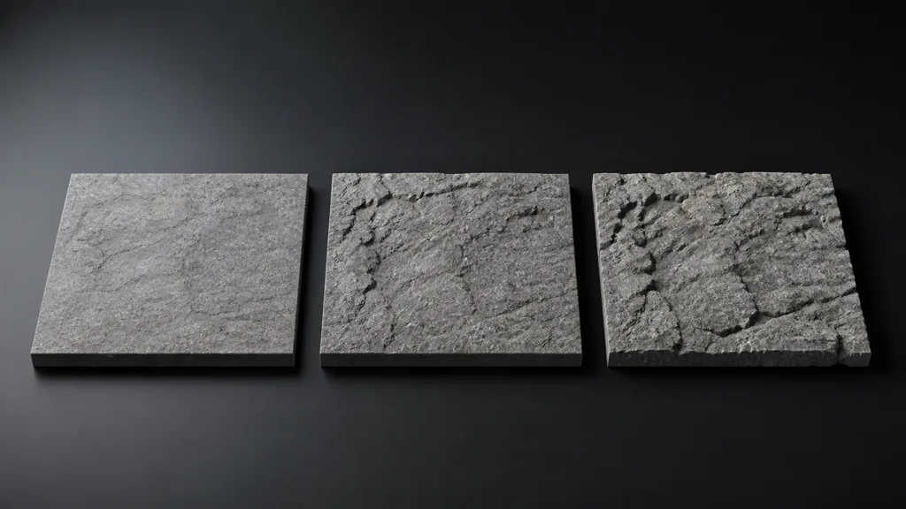
Parallax occlusion mapping vs displacement and normal mapping
| Technique | Best at | Cannot do | Main cost |
|---|---|---|---|
| Normal mapping | Fine surface lighting | Occlude texels or change silhouette | Texture sample and tangent-space shading |
| Basic parallax mapping | Cheap shallow UV shift | Resolve complex overlap well | Small number of height samples |
| Parallax occlusion mapping | Deep-looking inset relief | Change geometry or collision | Repeated per-pixel height samples |
| Displacement | Real silhouette and shadow detail | Stay cheap at arbitrary density | Geometry, subdivision, memory, and raster work |
In a parallax occlusion mapping vs displacement decision, inspect the silhouette first. A mostly planar wall viewed from inside a corridor can suit POM. A broken cliff rim against the sky needs geometry. For many assets the practical stack is modeled large forms, POM for medium inset depth, and normals for fine grain.
Build a stable POM shader workflow
- Choose eligible detail. Keep features inside the surface boundary and away from collision-critical edges.
- Import height as linear data. Verify the high/low convention with a simple ramp before testing a complex material.
- Set restrained physical amplitude. Match the represented material instead of compensating for weak lighting.
- Start with moderate steps. Confirm the ray direction and UV sign before spending samples on a reversed result.
- Refine the final interval. Interpolate between the last two layers so terraces do not dominate slow camera motion.
- Reuse the resolved UVs. Sample the complete PBR set from one parallax result.
- Scale quality by view. Increase layers toward grazing angles; reduce or fade them with distance and mip level.
- Profile approved scenes. Measure representative screen coverage, lights, overdraw, and material layers on target hardware.
The best parallax occlusion mapping workflow 2026 is not the one with the largest step slider. It is the lowest-cost configuration that remains stable in the actual camera envelope. A hero floor in a locked archviz shot and a reusable wall material in a fast third-person game have different budgets.
Tune steps, angle, depth, and self-shadowing
Use angle-dependent sampling: front-facing pixels need fewer layers because the ray crosses little texture-space distance, while grazing views need more. Set sensible minimum and maximum counts, then fade POM toward normal mapping when distance or mip level removes the useful height signal. This limits both cost and distant shimmer.
Self-shadowed variants march a second ray toward a light. They can deepen contact inside cavities, but the cost grows quickly and the result may only support a limited lighting model. Before adding another search, test whether restrained AO, engine contact shadows, or baked material response provides the intended read. Every ray march is concise until multiplied by a few million pixels.
Avoid interpreting step count in isolation. Texture cache behavior, dynamic branches, screen resolution, overdraw, material layering, and the number of maps sampled after the search all affect cost. Profile the complete shader, not a node sitting alone in a test graph looking innocent.
Parallax occlusion mapping in Unity, Unreal Engine, and Godot
For parallax occlusion mapping Unity workflows, Shader Graph exposes height, amplitude, step, LOD, parallax UV, and depth-offset concepts in supported configurations. Feed the resolved UVs to the coordinated map samples, connect depth offset where the active target supports it, and create a lower-quality fallback for pipelines or platforms where the full node is unsuitable.
In a parallax occlusion mapping Unreal Engine material, distinguish the cheaper Bump Offset path from a true multi-step POM function. Keep height ratio conservative, expose sample limits through material instances, and validate Pixel Depth Offset, contact shadows, temporal behavior, and platform compilation in the project’s current renderer.
For parallax occlusion mapping Godot, StandardMaterial3D and ORMMaterial3D provide height mapping, with deep parallax controls for minimum and maximum layers in supported renderers. Pair height with the normal map, test tangent and binormal orientation if motion looks reversed, and remember that built-in height mapping and triplanar mapping may not be compatible in the same material configuration.
Diagnose parallax occlusion mapping artifacts
| Symptom | Likely cause | Useful fix |
|---|---|---|
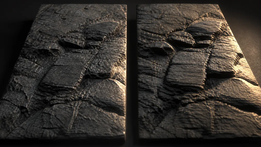
| Layers or terraces appear in motion | Too few steps or no final refinement | Add angle-dependent samples and interpolate the crossing |
| Cavities stretch at grazing angles | Depth is too high for the stored data | Reduce amplitude and fade near tangent views |
| Relief moves backward | Height, tangent, or view direction is inverted | Test a simple ramp and flip one convention at a time |
| Color and lighting separate | Maps use different UVs | Route one resolved coordinate set to every aligned map |
| Edges reveal a flat card | Expected limitation, not a sampling bug | Add geometry or avoid silhouette views |
| Performance collapses up close | High screen coverage and fixed maximum layers | Use tiers, distance fades, and representative profiling |
| Distant surface sparkles | Height detail outlives its mip resolution | Fade POM by distance or LOD and inspect the mip chain |
Debug with one grayscale height map, one neutral material, and a moving grazing camera. Disable self-shadowing and extra layers until the base intersection is stable. Reintroduce features one at a time; otherwise five clever systems can collaborate on one very ordinary artifact.
Try CraftPBR
CraftPBR creates the coordinated maps a parallax occlusion mapping setup needs:
- Text-to-PBR generates a complete material from a physical surface description.
- Photo-to-PBR converts a controlled reference into aligned height, normal, color, and roughness maps.
- Node workspace keeps height range, tile cleanup, roughness, and material variations editable.
- Engine export prepares normal orientation, map naming, channel layouts, and destination-specific files.
- Free tier lets you build and test a complete PBR set before committing it to a production shader.
- CC0 output lets you modify, render, and ship generated textures without attribution.
Spend samples on depth the camera can see. Model the depth it can catch lying.