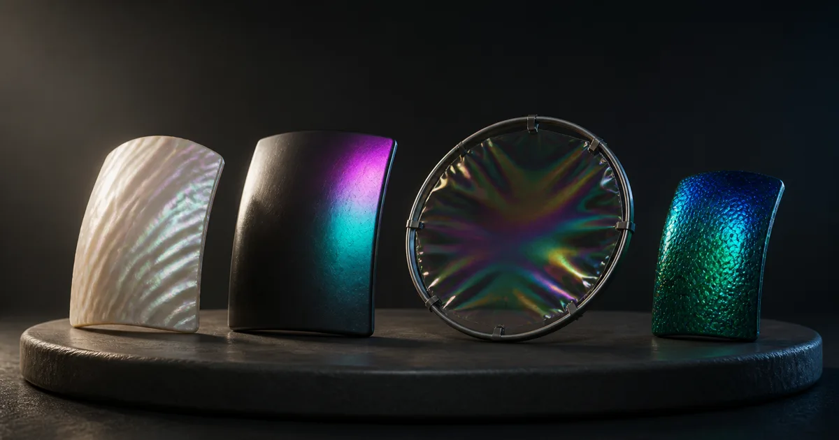
Put a coated sphere on a turntable and render one still. Almost any rainbow gradient can look convincing. Rotate the camera twenty degrees, and the lie starts sliding across the object like a loose rug. Iridescent materials change with view and light direction, so motion is not presentation; it is the test.
A useful material separates stable body color from an angle-dependent optical layer. It gives roughness, normals, thickness, and masks different jobs, then survives neutral light and several shapes.
This guide treats iridescent materials as an optical system rather than a multicolor image. The goal is controlled motion: enough spectral change to reveal the coating, not so much that a door hinge appears to have swallowed a prism.
What iridescent materials are actually doing
In a common thin-film model, light reflects from the top of a transparent microscopic layer and again from the boundary beneath it. Those paths travel different distances. Depending on wavelength, film thickness, refractive index, view angle, and light angle, the reflected waves reinforce or cancel one another. The visible result is PBR iridescence: hue and intensity shift as the geometry, camera, or light moves.
The underlying material still matters. Dark coated metal can keep a nearly black body beneath cyan reflections. Nacre combines layers with scattering; soap film is translucent; oxide sits over a conductive base. One slider cannot make them interchangeable.
Three observations keep the shader honest:
- the color shift belongs mainly to the specular response, not a painted diffuse rainbow;
- smooth curvature reveals an ordered angular transition, while flat surfaces may show one narrow band;
- more roughness blurs and weakens the spectral pattern instead of merely lowering saturation.
A real thin film interference material is also sensitive to thickness. Uniform thickness produces an orderly shift across changing angles. Small thickness variation breaks that response into related patches. Wild noise creates confetti, which is useful only when the art brief explicitly requests “scientific instrument after a craft-store incident.”
Name the optical effect before building the shader
Several effects can produce changing or multicolored surfaces, but they do not share the same controls.
| Effect | Physical cue | Useful controls | Typical examples |
|---|---|---|---|
| Thin-film interference | Spectral reflection changes with angle and film thickness | Film IOR, thickness, roughness, normal | Soap film, oxide, coated metal |
| Layered nacre | Directional color from microscopic platelets plus body scattering | Layer orientation, flake response, roughness | Pearl, shell, some paints |
| Structural coloration | Microstructure selects wavelengths by geometry | View/light direction, pattern scale | Insect-inspired coatings, feathers |
| Diffraction | Fine periodic grooves split light strongly | Groove spacing and direction | Holographic foil, compact disc |
| Anisotropy | Highlight stretches or rotates with tangent direction | Tangent map, anisotropy, roughness | Brushed metal, satin |
| Colored clear coat | A second specular lobe over a substrate | Coat weight, coat IOR, coat roughness | Lacquer, varnish, automotive paint |
An iridescent texture may support any of these, but it does not identify the model. Diffraction needs directional microstructure, pearl flakes need orientation, and thin film needs optical thickness. Anisotropy changes highlight shape, not necessarily spectral color; the anisotropic materials guide covers that distinction.
Layering effects is valid when the reference calls for it. An iridescent car paint material can combine metallic flakes, a tinted base, thin-film response, and a clear top coat. Build and validate each lobe separately before stacking them. Otherwise one wrong highlight can hide another with remarkable professional confidence.
Thickness, IOR, angle, and roughness form one control system
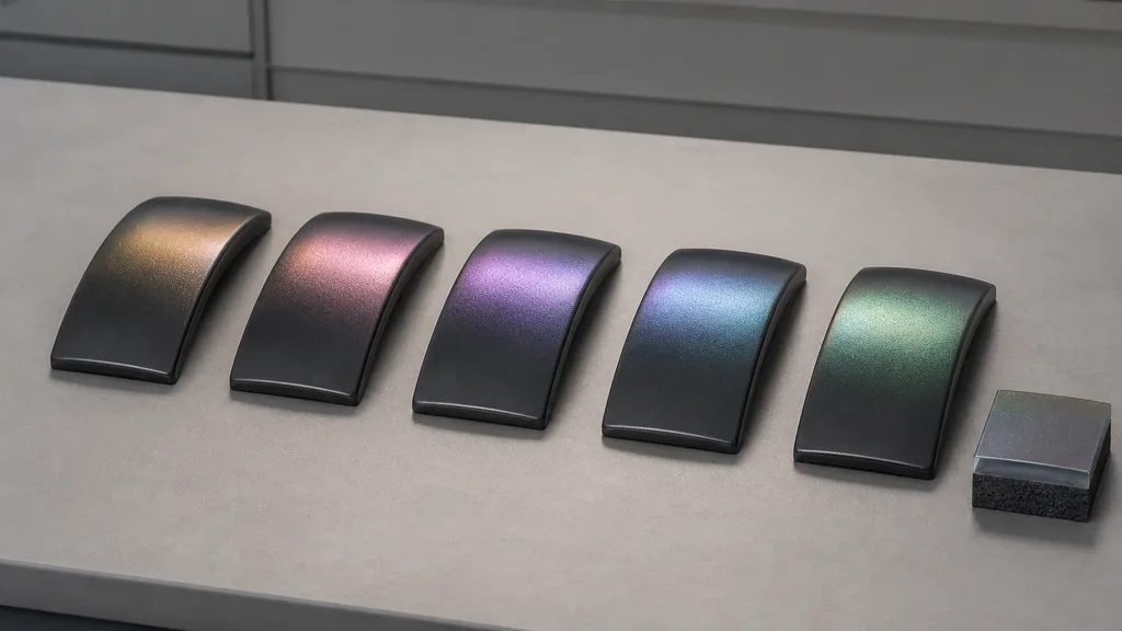
The core parameters of iridescent materials are coupled:
- film thickness changes which wavelengths reinforce at a given angle;
- film IOR changes the reflection at each boundary and the optical path through the film;
- surface normal changes the local incidence and view angles;
- roughness spreads those angles across a microfacet distribution, broadening the response;
- substrate F0 or metal behavior determines the reflection beneath the film;
- lighting spectrum determines which wavelengths are available to reflect.
Start with constant film thickness on a smooth sphere under neutral white lights. Sweep the range slowly, then introduce roughness. Add normal detail only after the broad color travel behaves. This keeps each change visible instead of asking five sliders for a joint alibi.
A thin film thickness map should usually vary gently. Large coherent regions can represent oxide growth, coating flow, stretched film, or wear. Fine noise belongs in roughness and normals unless the reference proves that the optical thickness changes at that scale. Keep the map linear and document how its 0–1 range maps to the renderer’s physical or normalized thickness.
Do not bake colored highlights into base color. Rotate the light off, inspect the diffuse or body component alone, and confirm that the rainbow mostly disappears. For an oil slick material PBR treatment, the substrate may remain dark while film thickness creates moving bands. For a pearl material PBR treatment, a pale body and layered scattering can remain visible after the angular reflection is isolated.
Build texture maps that describe causes, not the final screenshot
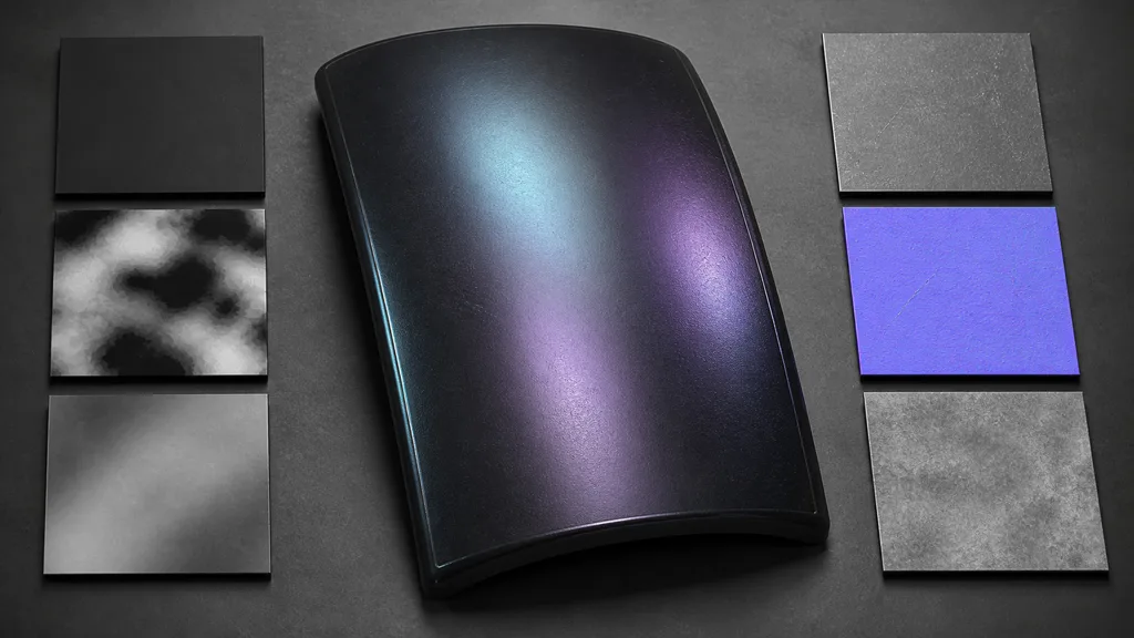
An iridescent texture set can stay compact if every map has a specific responsibility:
| Input | Responsibility | Useful authoring rule |
|---|---|---|
| Base color | Stable body or substrate color | Remove colored reflections and cast light |
| Iridescence mask | Where the optical layer participates | Follow coating boundaries, chips, dirt, and exposed substrate |
| Film thickness | Local optical thickness | Use broad causal variation; keep values linear |
| Roughness | Width and clarity of the reflection | Coordinate polish, fingerprints, abrasion, and weathering |
| Normal | Surface orientation below pixel scale | Preserve believable microstructure without painting hue |
| Height | Actual relief for blending or parallax | Reserve for geometry-like depth, not spectral bands |
| Metalness | Substrate classification in a metalness workflow | Do not make the transparent film itself “metal” |
Wear should affect related maps together. A scratch can remove PBR iridescence, expose substrate roughness, and add a shallow normal. Dust may raise roughness and reduce the mask without cutting the film. Cause first; channels second.
Pack linear masks only when the engine import and compression suit all of them. The texture channel packing guide explains channel contracts, and the sRGB vs linear textures guide covers why a thickness mask must not receive a color decode.
How to make an iridescent material step by step
- Choose one physical reference. Name soap film, titanium oxide, pearl, coated polymer, nacre, or another specific construction.
- Separate the layers. Identify body color, substrate reflection, optical film, surface roughness, flakes, dirt, and damage.
- Lock a neutral test rig. Use a sphere, broad white lights, a neutral environment, fixed exposure, and no colored fill.
- Set the substrate first. Match base color, metalness or specular response, and ordinary roughness with iridescence disabled.
- Enable a constant film. Tune IOR and one thickness value until the angular sequence resembles the reference.
- Define the thickness range. Find the narrow useful interval before adding a thin film thickness map.
- Add masks and wear. Place the coating where the manufacturing or natural process would leave it, then connect damage across maps.
- Test motion and lighting. Rotate camera, object, and light independently; compare flat, curved, and folded forms.
- Translate to the target engine. Match units and feature support, then profile the actual build and make a bounded fallback.
The best iridescence workflow 2026 stores the reference, film model, thickness range, IOR, texture meanings, and fallback beside the asset. A screenshot of the node graph is not documentation unless the next artist enjoys archaeology.
Iridescent materials in Unity, Unreal Engine, and Blender
For iridescent materials Unity projects, HDRP Lit exposes an Iridescence material type with an Iridescence Mask and Iridescence Layer Thickness control. Start with the mask at a constant value and a narrow thickness remap, then feed authored linear data after the response is proven. Unity’s HDRP Material Type documentation describes the dedicated inputs. URP does not mirror the full HDRP Lit model, so use Shader Graph or custom shader code and compare the approximation on every supported renderer path.
For an Unreal Engine iridescence material, current Substrate documentation includes a Thin-Film helper that computes specular parameters from film properties, and Epic demonstrates thin-film interference within layered Substrate materials. Substrate is still marked Beta in the current documentation, so verify shipping support, GBuffer cost, platform settings, and fallbacks before committing an entire material library. Epic’s Substrate Materials documentation is the authoritative starting point. A custom legacy material function can approximate the color shift where Substrate is unsuitable, but keep it energy-aware and bounded.
For a Blender iridescent material, the Principled BSDF includes an Iridescence weight plus IOR and thickness controls. Use Cycles or Eevee according to the delivery renderer, drive thickness with linear data, and test the same node setup under camera and light motion. Blender’s Principled BSDF manual documents the inputs. If an older target version lacks the required controls, a layered Fresnel and spectral-ramp approximation can work for art direction, but it is not identical to a thin-film solver.
Engine numbers are not automatically portable. Match observed color travel under the same reference rig rather than copying a slider value with heroic optimism.
Budget the effect without freezing the color
The cost of iridescent materials depends on the model. Thin-film evaluation adds angular and spectral math; layers add BRDF work. Flakes, translucency, parallax, clear coat, and extra samples may cost more than iridescence itself.
Build quality tiers around visible cues:
- Hero: physical thin film, thickness variation, layered substrate, high-quality reflections, and correct roughness.
- Standard: bounded thin-film approximation with one mask and one thickness channel.
- Low: a view-dependent two- or three-color ramp constrained to the specular lobe.
- Distant: stable body material with restrained Fresnel tint or no iridescence when the effect is below a pixel.
Do not freeze the rainbow into base color as the first fallback. That preserves the palette and deletes the phenomenon. A cheaper view-dependent ramp communicates what makes a material iridescent better than a detailed static bitmap.
Measure shader variants, instruction count, texture bandwidth, reflection method, overdraw, and temporal behavior in the shipping scene. Soap film may also require transparency, which changes the budget radically. An opaque coated prop and a translucent bubble should not share a performance estimate because both happen to contain purple.
Prove iridescent materials with motion and neutral light
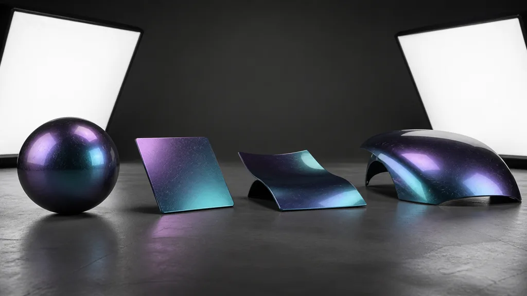
Validate iridescent materials on at least four shapes. A sphere shows the full angular gradient. A flat chip proves the response does not require convenient curvature. A folded sheet tests abrupt normal changes. A broad panel exposes repetition, roughness, and environment dependence.
Run four short captures:
- fixed object and light, moving camera;
- fixed camera and light, rotating object;
- fixed camera and object, moving white light;
- production camera and lighting with the approved tone map.
The response should travel continuously, follow reflection geometry, soften as roughness rises, and preserve the substrate. Check mipmaps on masks and thickness data; high-frequency variation can sparkle at distance. Test temporal anti-aliasing and upscalers in motion.
Compare a neutral render with the reference. If the material needs a cyan environment to look cyan, it may be reflecting the room rather than producing interference. If every face shows a full rainbow, the thickness range is too broad. If nothing moves, confirm view vectors, normals, feature support, and the active shader variant.
FAQ
What makes a material iridescent?
A material appears iridescent when its reflected spectrum changes with view or light angle. Thin-film interference, layered microstructures, diffraction, and structural coloration can produce the effect, so the correct shader depends on the physical reference.
How do you make an iridescent material?
Build the ordinary substrate first, then add an angle-dependent optical layer with controlled IOR, thickness, mask, normals, and roughness. Test it under neutral light while moving camera, object, and light independently.
Is iridescence the same as metallic?
No. Metalness describes how the base surface reflects and absorbs light, while iridescence describes wavelength-dependent change caused by a film or microstructure. An iridescent coating can sit over a metal or a dielectric substrate.
Why does my iridescent material look like a rainbow texture?
The hue may be painted into base color, the spectral ramp may cover too wide a range, or the effect may ignore view angle and roughness. Isolate the body color, narrow the film thickness range, and confirm the response moves with reflection geometry.
Do iridescent materials need a thickness map?
Not always. A constant thickness is appropriate for a uniform manufactured coating, while oxidation, stretched films, nacre, and worn finishes may need a controlled map. Use a map only when local thickness variation has a physical cause.
How do I make an iridescent material in Blender?
Use the Principled BSDF Iridescence controls, set the substrate first, then tune iridescence weight, IOR, and thickness under neutral lighting. Drive thickness with linear texture data when the coating varies and validate in the renderer you will deliver.
Are iridescent shaders expensive?
A basic thin-film approximation is often manageable, but layered BRDFs, flakes, transparency, reflections, and extra texture samples can raise the cost. Profile the complete material on target hardware and provide a view-dependent ramp or simpler substrate for lower tiers.
Try CraftPBR
CraftPBR builds the coordinated surface data that sits beneath and controls iridescent materials, while the destination shader computes the angle-dependent optics:
- Text-to-PBR generates a full material set from a description of substrate, coating, scale, polish, wear, and damage.
- Photo-to-PBR converts a controlled surface photo into aligned base color, normal, roughness, height, AO, and metalness maps.
- Node workspace keeps masks, thickness variation, roughness, levels, tiling, and related coating variants editable.
- Engine export prepares normal orientation, linear masks, packing, filenames, and target-specific map conventions.
- Free tier lets you create and test a complete surface set before building the thin-film shader.
- CC0 output lets you modify, render, and ship generated textures without attribution.
Make the color move for a reason. The camera will check your paperwork.