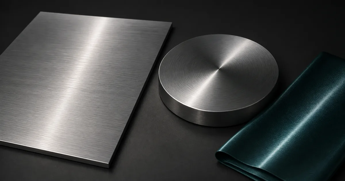
Anisotropic materials reflect light differently depending on direction. A brushed aluminum panel, a turned steel dial, and a ribbon of satin can share the same average roughness yet produce radically different highlights because their microscopic structure is aligned rather than random.
That direction is the entire effect. Ordinary isotropic shading assumes surface irregularities have no preferred orientation, so the specular lobe spreads evenly around the normal. Anisotropic shading gives the lobe two different widths and orients them with a tangent field. The result can stretch, rotate, or curve across an object as the camera and light move.
This guide treats anisotropy in PBR as material evidence, not a slider reserved for shiny cookware. We will separate strength from direction, build maps from manufacturing logic, handle UV and tangent seams, and set up the result in Blender, Unreal Engine, and Unity HDRP.
How anisotropic materials reshape a reflection
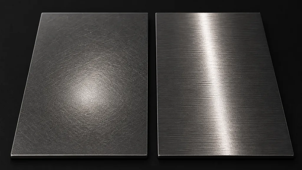
To answer how does anisotropic shading work, begin below the resolution of the texture. PBR reflection models approximate countless tiny surface facets. When their slopes are distributed equally in every horizontal direction, a reflected point or strip light forms a roughly round or symmetric lobe. When machining, extrusion, fibers, or repeated abrasion aligns those slopes, the lobe becomes narrower in one tangent direction and wider in the perpendicular direction.
The visible highlight often appears stretched across the brushing rather than along each scratch. That can feel backward until you remember that the grooves describe microfacet orientation, not a painted streak of light. Different shaders expose positive and negative anisotropy or rotate the tangent convention, so a reference sphere is more trustworthy than the sign printed beside a slider.
Brushed metal anisotropy is the standard example because fine machining lines remain coherent over large areas and metal reflections make the lobe easy to see. The same principle applies to satin yarns, hair fibers, vinyl records, carbon-fiber layups, extruded plastic, and wood finished along the grain. Useful anisotropic materials begin wherever the surface process has a direction the light can discover.
Separate anisotropic roughness, strength, and direction
Stable anisotropic materials keep three controls conceptually separate. Base roughness defines the overall reflection spread. Anisotropic roughness or strength makes that spread unequal between two perpendicular axes. The tangent field rotates those axes across the surface. Changing all three at once is a reliable way to produce an attractive result whose cause nobody can explain later.
| Control | Physical question | Typical failure |
|---|---|---|
| Roughness | How broad is the reflection overall? | Compensating for weak anisotropy by polishing the whole surface |
| Anisotropy strength | How unequal is roughness between the two axes? | Maxing the value until every surface resembles machined foil |
| Tangent direction | Which way does the material structure flow? | Highlights snapping or spiraling at UV seams |
| Strength mask | Where is the directional structure preserved? | Adding grayscale noise unrelated to wear or manufacture |
Normal maps and anisotropic texture data also do different jobs. The normal map changes the local surface normal, creating dents, waviness, weave relief, or wider scratches. A tangent or direction map rotates the preferred reflection axis around that normal. Baking the brushing only into normals can suggest grooves, but it does not give a renderer with anisotropic support the correct elongated lobe.
Keep strength and direction data linear. They are numeric controls, not display colors. If the destination expects a signed vector or a centered rotation value, document the encoding beside the export preset; a mysterious purple-green image named final_dir_2.png is not documentation, despite its confidence.
Author an anisotropy direction map from the real process
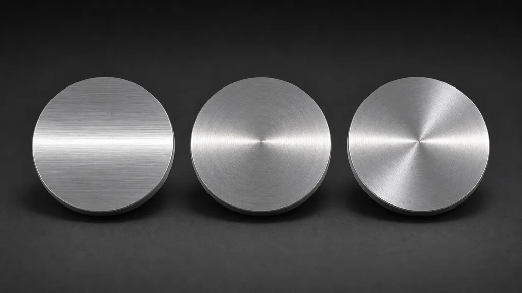
In anisotropic materials, an anisotropy direction map should describe a flow field. Straight-brushed sheet can use one mesh tangent over the whole part. A lathe-turned disc needs concentric flow. A radial sunburst finish points away from the center. Woven fabric may alternate warp and weft influence, while hair cards follow strands from root to tip.
Start by drawing sparse guide curves over the UV layout or generating them from a known procedural coordinate system. Convert those curves into the vector convention required by the renderer, then inspect the field directly before connecting it to shading. Look for sudden rotations, zero-length vectors, flipped islands, and singularities near centers. Radial and concentric fields need special handling at their origin because every direction meets one texel that cannot satisfy all of them.
Do not copy the base-color grain and assume it is a direction map. Color can contain stains, oxidation, weave shadows, print, and lighting that say nothing about tangent flow. Likewise, a grayscale scratch mask can control anisotropy strength but cannot express a two-dimensional direction without an agreed encoding.
How to make an anisotropic material step by step
Build anisotropic materials by proving one variable at a time:
- Name the process. Decide whether the direction comes from brushing, turning, weaving, combing, extrusion, rolling, or repeated wear.
- Build the ordinary PBR base. Establish measured base color, metallic behavior, and average roughness before adding directionality.
- Test a constant tangent. Use a simple plane, neutral environment, and large area light. Raise anisotropy until the lobe matches a reference, not until it becomes most visible.
- Create the flow field. Keep a uniform mesh tangent for straight brushing or author a map for radial, curved, or locally changing direction.
- Add causal variation. Reduce strength where dust, fingerprints, coating, corrosion, or cross-scratches disrupt the aligned microstructure.
- Rotate both object and light. Direction errors can hide in one still and announce themselves during motion.
- Export to the destination convention. Confirm tangent space, channel use, signed range, texture color space, and whether the engine supports the chosen shading path.
The best anisotropic material workflow 2026 begins with a boring test object. A plane reveals sign and orientation; a cylinder reveals seam continuity; a disc reveals whether circular flow is genuinely circular. Only then move to the hero asset, where bevels, mirrored UVs, layered coatings, and art direction will all volunteer to obscure the original problem.
Choose surfaces where directional shading earns its cost
Anisotropic materials are useful when directional highlights contribute to recognition. Brushed appliance steel, spun cookware, machined knobs, satin, silk, hair, and carbon fiber change character as the highlight moves. The effect is weaker on chalk, unpolished stone, diffuse paint, or heavily corroded metal because broad random scattering overwhelms the aligned structure.
Not every visible line requires anisotropy. Good anisotropic materials still assign coarse saw marks to normals and roughness, and deep grooves may need geometry or displacement. A lacquered wood surface can have a mostly isotropic clear coat above directional fibers. Layer the physical causes in the correct order rather than forcing one lobe to impersonate an entire material stack.
- Use a constant direction for large sheet stock with one uninterrupted brushing pass.
- Use a direction map for turned, radial, woven, combed, or bent flow.
- Use a strength mask where residue, paint, oxidation, or wear interrupts the aligned finish.
- Skip anisotropy when the final camera, lighting, or roughness cannot reveal it.
Anisotropic material setup in Blender, Unreal Engine, and Unity
For an anisotropic material Blender setup, the Principled BSDF exposes anisotropic weight and rotation controls, while a Tangent node or tangent input can provide flow derived from a UV map or radial axis. Test in the shipping render engine because feature behavior and support can differ. Blender’s Principled BSDF documentation is the right reference for the current node inputs.
An anisotropic material Unreal Engine uses the Anisotropy input for amount and the Tangent input for direction. Epic documents a -1 to 1 anisotropy range, with zero producing an isotropic response; supported rendering paths and scalability still need validation on target hardware. See Epic’s Material Inputs reference rather than copying a graph from an older project whose assumptions have quietly fossilized.
For an anisotropic material Unity project, HDRP’s Lit material supports an Anisotropy material type with strength and tangent-map controls. Unity’s HDRP material-type reference documents those inputs, while the render-pipeline comparison lists anisotropic lighting in HDRP rather than the standard Built-in or URP lighting models. Confirm pipeline scope before authoring a large texture set; use Shader Graph or custom shading only when the destination and maintenance budget justify it.
Diagnose broken anisotropic shading
| Symptom | Likely cause | Useful test |
|---|---|---|
| Highlight does not stretch | Anisotropy is zero, unsupported, or hidden by very high roughness | Use a polished test plane and constant mid-high strength |
| Highlight runs 90 degrees wrong | Tangent convention or sign differs | Rotate the direction once instead of repainting the source |
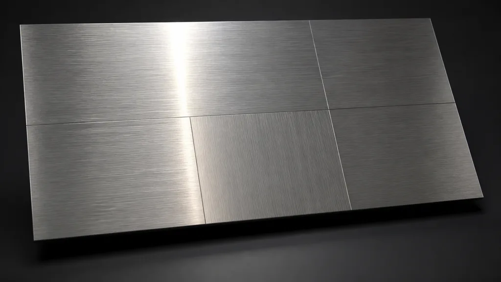
| Seams flash during motion | Mirrored UVs or discontinuous tangent basis | Visualize tangents and test islands without the normal map |
| Disc center forms a pinwheel artifact | Radial-field singularity or poor filtering | Mask the center, improve sampling, or hide it with geometry |
| Surface looks like holographic foil | Strength is excessive or the flow contains noisy rotation | Reduce anisotropy and remove nonphysical vector noise |
| Result changes after export | Color-space, channel, or tangent-space mismatch | Export a constant field and compare numeric samples |
Debug anisotropic materials with a white area light moving across a neutral object. Disable color texture, clear coat, detail normals, and grime until roughness, strength, and direction agree. Then restore one layer at a time. A shader graph is perfectly capable of hiding three orientation bugs beneath a tasteful fingerprint mask.
Try CraftPBR
CraftPBR builds the coordinated surface data that supports convincing anisotropic materials:
- Text-to-PBR generates a complete material from a physical description such as fine linear brushed aluminum or dark woven satin.
- Photo-to-PBR turns a controlled surface reference into aligned color, normal, height, and roughness maps.
- Node workspace keeps directional grain, roughness breakup, normal detail, and material variations editable.
- Engine export prepares map orientation, naming, channel layouts, and destination-specific files.
- Free tier lets you create and validate a complete PBR set before building the final shader.
- CC0 output lets you modify, render, and ship generated textures without attribution.
Give the highlight a direction because the material has one, not because the slider looked lonely.