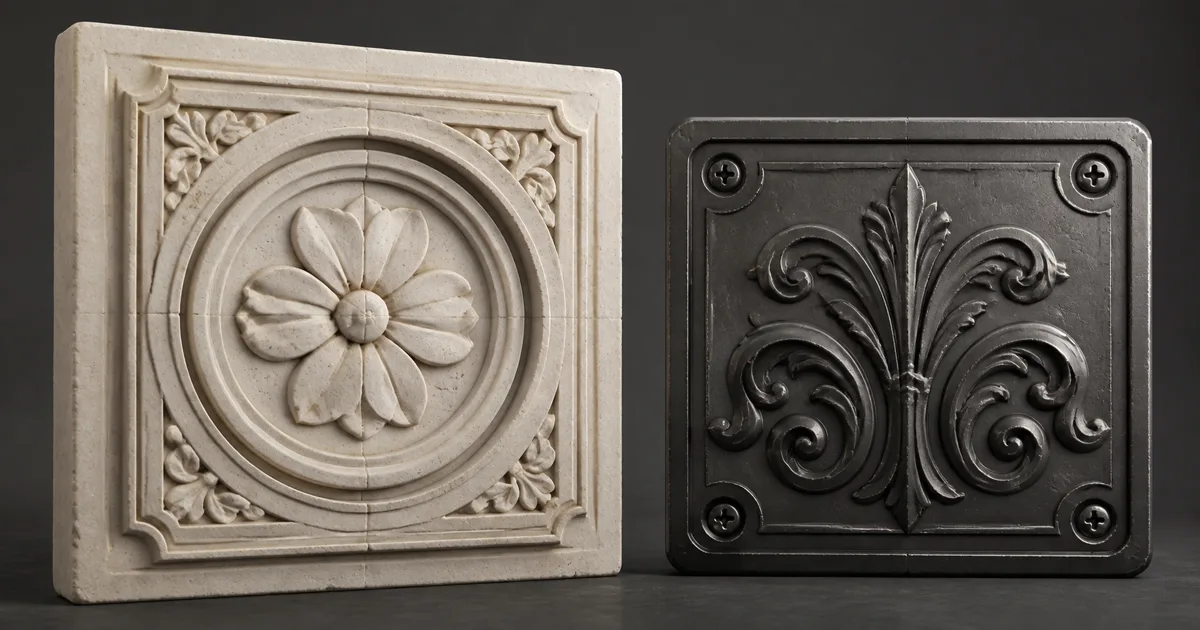
Bake the same decorative panel with a 2 mm ray distance and a 2 m ray distance. Both outputs may be called ambient occlusion. Only one knows that a hairline engraving is not a doorway.
A cavity map is a short-range visibility mask for tiny recesses: pores, cracks, panel seams, stitching, engraved lines, screw sockets, and details that may exist only in the high-poly bake or normal map. Its job is to preserve micro-occlusion that real-time lighting cannot reliably recover from the low-poly silhouette. It should not install permanent evening lighting across the whole asset.
That scale boundary is the entire technique. A good cavity map gives a shader or material graph a compact answer to “is this texel inside a small local recess?” A bad one is ordinary broad AO renamed after someone moved a slider.
A cavity map is short-range visibility data
Most bakers create a cavity map with the same ray test used for ambient occlusion, but with a deliberately short maximum distance. Rays leave the surface, nearby geometry blocks some of them, and the visible fraction becomes a grayscale value. White usually means open; darker values mean locally enclosed.
The short radius makes the output a micro occlusion map. A narrow groove can darken while the center of a large arch remains nearly open. The renderer already has other systems for broad visibility.
A PBR cavity map is derived geometric data, not a fundamental property like base color or roughness. Its values change with mesh detail, bake distance, scale, and occluders. Document the measurement range.
The ambient occlusion map guide covers the broader visibility term.
Cavity map vs ambient occlusion vs curvature map
The useful comparison is not which grayscale image looks moodiest. It is what neighborhood each one measures and what question it answers.
| Map | Typical measurement | Best question | Common misuse |
|---|---|---|---|
| Cavity | Very short-range occlusion | Is this texel inside a tiny recess? | Multiplying broad base color until every groove looks dirty |
| Ambient occlusion | Wider local visibility | How enclosed is this surface region? | Replacing dynamic lighting or direct shadows |
| Curvature | Change in surface orientation | Is this area convex, concave, or flat? | Treating curvature as physically measured shadow |
| Normal | Local surface direction | Which way should fine detail shade? | Assuming the renderer can infer hidden micro-visibility from it |
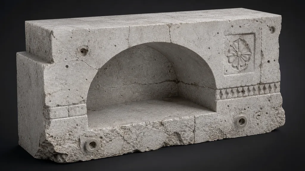
In a cavity map vs ambient occlusion test, ray distance is the decisive variable. Broad AO may darken the floor of an arch, the corner of a room, and the gap below a machine. A cavity bake should ignore those large structures and retain only tight seams and pores. If both maps are nearly identical, the cavity distance is probably too large or the asset contains no useful scale separation.
The cavity map vs curvature map distinction is visibility versus shape change. Curvature can highlight exposed convex edges and identify concave valleys even when nothing significantly blocks the hemisphere. A cavity map only reports local enclosure. Use curvature for wear, edge masks, and shape-aware texturing; use cavity when tiny recessed detail needs a visibility or material-blending cue. The curvature map guide explains that measurement in depth.
Choose cavity scale from the shipped texel footprint
“Short” needs units. A ray distance of 0.01 means nothing until the scene scale says whether that is a millimeter, centimeter, or small shed. Start from the largest recess that should count as microdetail, then compare it with the texture resolution and expected on-screen size.
For a 2K prop texture covering one meter, a single texel spans roughly half a millimeter before UV inefficiency. A 2–5 mm cavity map radius can preserve grooves several texels wide without swallowing a 10 cm panel inset. The same numeric distance on a building facade or jewelry asset would be nonsense in opposite directions.
Three checks keep the scale defensible:
- World-space size. Measure representative seams, pores, bevel roots, and recesses on the final asset.
- Texel size. Confirm the detail survives the bake resolution and UV layout. A sub-texel cavity becomes an unstable average, not hidden treasure.
- Shipped distance. Force expected mip levels. If the feature disappears by mip three, decide whether the averaged signal should fade, remain, or move into another representation.
Increasing ray distance cannot restore a groove lost below texture resolution. It only catches larger geometry and recruits the surrounding panel into the crime scene.
How to bake a cavity map without importing the bake room
Good cavity map baking is mostly a disciplined distance experiment.
- Lock final scale and topology. Apply transforms, triangulate as required, freeze UVs, and use the actual low-poly shading setup.
- Choose relevant occluders. Include stable high-poly detail that belongs to the asset. Exclude floors, turntables, temporary bolts, nearby props, and moving attachments.
- Start with a tiny ray distance. Use a world-space value near the largest intended groove width, not a percentage guessed from the bounding box.
- Bake a distance ladder. Produce three or four variants, for example 1×, 2×, 4×, and 8× the starting radius, with every other setting fixed.
- Select by exclusion. Keep the smallest distance that captures required recesses; reject the first variant that begins shading broad panels or neighboring parts.
- Clean projection errors. Cage intersections, skewed rays, hard-normal seams, and mismatched high-poly parts can make black marks unrelated to visibility.
- Dilate UV islands. Give lower mips enough padding so white background does not leak into dark seams or dark islands into open surfaces.
- Export as linear data. Preserve numeric values, avoid sRGB conversion, and choose compression by the artifact budget rather than the thumbnail.
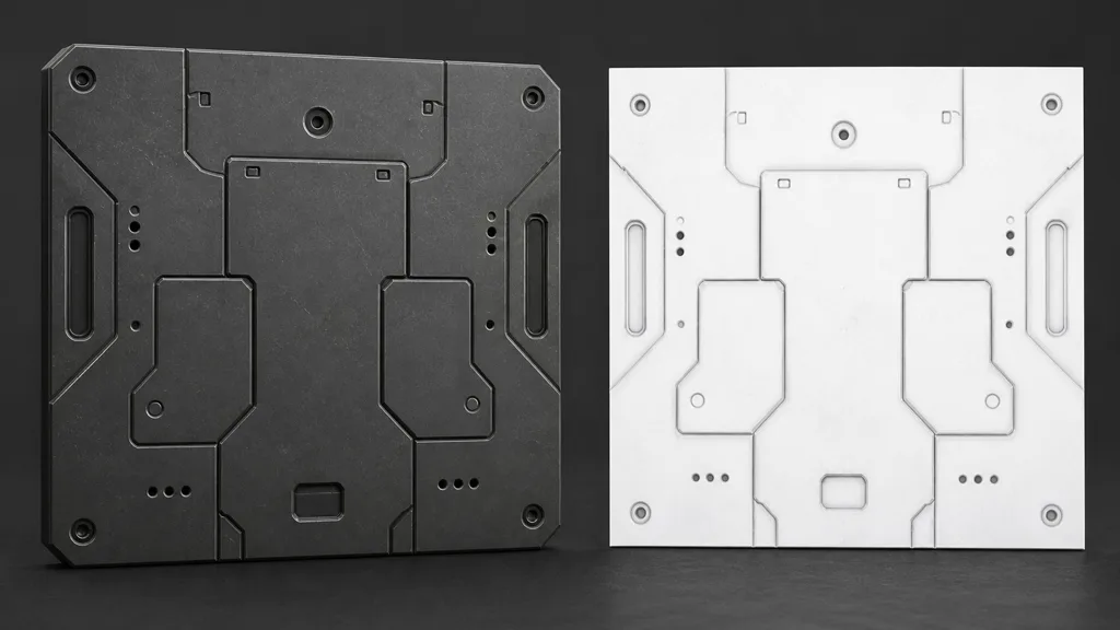
If the baker exposes spread angle, bias, falloff, or attenuation, change one control at a time. Establish participating geometry through distance first; then shape the response.
Use cavity as a signal, not a second lighting pass
There is no universal cavity socket. That is useful: it forces the pipeline to state why the data exists.
Common uses include subtle ambient or specular micro-occlusion, masks for polish variation, stylized seam separation, and procedural wear. Keep each use independently adjustable. One value should not secretly darken color, crush reflections, and add dirt.
For physically based lighting, prefer applying short range ambient occlusion to indirect visibility rather than direct light. A cavity should not erase a direct highlight from a light that can plainly reach the groove. Directly multiplying base color is an art-direction fallback; it bakes darkness into albedo and can double-darken when AO or GI also responds.
For a stylized color multiply, cap the strength and validate under bright flat light. Clean white ceramic should not grow charcoal grout merely because its ornament has depth.
| Use | Sensible treatment | Warning |
|---|---|---|
| Indirect micro-occlusion | Remap gently into the supported occlusion path | Broad AO may stack with it |
| Specular micro-occlusion | Reduce impossible reflection in subpixel recesses | Do not remove the whole dielectric boundary response |
| Dirt or polish mask | Feed a separate material-specific blend | A recess is not automatically dirty |
| Stylized readability | Apply a capped color factor | Lighting changes cannot remove baked color |
| Packed utility channel | Store with maps sharing UVs, mips, and color space | Channel labels must survive export |
Cavity map setup in Unreal Engine, Unity, and Blender
For a cavity map Unreal Engine material, Epic describes cavity as an AO bake with a very short trace distance and documents multiplying it into final Base Color and the default Specular value. That is a concrete legacy-friendly recipe, not a command to maximize contrast. Test it against the project’s current GI and material path, expose strength, and compare an Ambient Occlusion-only treatment when base-color multiplication looks baked. See Epic’s Physically Based Materials documentation.
For a cavity map Unity setup, URP Lit exposes an Occlusion Map that reduces ambient light and reflections in crevices. A short-range cavity texture can feed that slot when its meaning matches the desired occlusion, but a custom Shader Graph is safer when broad AO and cavity need different strengths or packed channels. Unity’s URP Lit Shader reference documents the occlusion input.
For a cavity map Blender workflow, the Cycles Ambient Occlusion node exposes Distance and Only Local controls, which make a short-range look-development test possible. For portable assets, bake the result and use it as a restrained mask or factor in the target material. Blender’s Ambient Occlusion node manual documents the distance-controlled signal.
Across engines, do not assume identical semantics. Some occlusion inputs affect indirect diffuse, reflections, baked lighting, or only certain lighting paths. Verify the exact renderer version and inspect the final buffer, not just the material preview.
Pack, filter, and mip the cavity map deliberately
A cavity map texture is linear scalar data. Disable sRGB. If it shares a texture with roughness, metalness, or AO, keep the channel convention explicit in filenames and export presets. The texture channel packing guide covers compatible data and mip behavior.
Compression can erase a one-pixel groove or create blocks around it. Test the target GPU format; a clean single-channel format may justify its cost for dense seams.
Straight mip averaging pushes sparse dark cavities toward white, often matching their shrinking screen coverage. For stylized readability, author a controlled response or move the cue to geometry, decals, or roughness. Do not sharpen remote props into black pores.
Padding must cover the lowest useful mip. Mirrored or stacked UVs are safe only when the participating geometry should share identical cavity values. A unique bolt shadow baked onto a stacked panel is not optimization; it is duplication with confidence.
Validate cavity maps by subtracting them
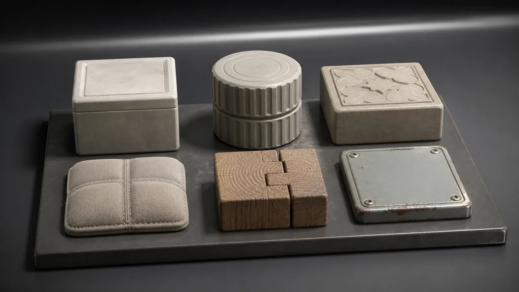
Build a test set with a smooth bevel, narrow groove, engraved tile, stitch seam, wood joint, screw recess, and one broad cavity. Render four states at fixed exposure: no cavity, cavity only in the intended lighting path, maximum debug contrast, and the full shipped material.
Then ask concrete questions:
- Does the broad cavity remain controlled by real lighting rather than the cavity map?
- Do small recesses stay attached to geometry under moving light without looking painted?
- Does the effect survive the intended mip, compression, and platform quality?
- Does removing the map reveal a real production loss at shipped distance?
- Does dynamic AO stack into black seams?
- Can an artist reduce or disable the effect without rebuilding textures?
The last question matters. If the cavity map has no visible benefit, delete the sample. A grayscale texture is not free merely because it fits into a channel that appeared lonely.
The best cavity map workflow 2026 documents scale, ray distance, occluders, channel, import mode, shader use, and fallback. Seven boring facts prevent many dramatic screenshots.
FAQ
What is a cavity map?
A cavity map is a short-range occlusion texture that identifies tiny recessed surface details such as pores, cracks, seams, and engravings. It is usually grayscale, with open areas near white and enclosed microdetails darker.
How does a cavity map work?
A baker casts rays from each surface texel and measures how many are blocked within a small maximum distance. Limiting that distance separates micro-occlusion from the broader enclosure captured by a conventional AO map.
What is the difference between a cavity map and an ambient occlusion map?
A cavity map uses a much shorter measurement radius and targets fine local recesses. Ambient occlusion usually covers larger corners, gaps, and enclosed regions, so the two signals may need separate strengths or uses.
Is a cavity map the same as a curvature map?
No. A cavity map measures short-range visibility, while a curvature map measures how surface orientation changes. Concave curvature can resemble cavity data, but curvature can also identify exposed convex edges and does not directly measure occlusion.
How do you bake a cavity map?
Bake AO with final asset scale, relevant self-occluders, and a short world-space ray distance. Test a distance ladder, choose the smallest radius that captures required grooves, fix projection artifacts, pad UV islands, and export the result as linear data.
Should a cavity map be sRGB?
No. It is numeric mask data and should normally be imported without sRGB conversion. Verify channel packing and compression in the destination engine because both can change small dark features.
Do I need a cavity map if I already have ambient occlusion?
Not always. Use a separate cavity map only when broad AO cannot preserve important high-frequency recesses or when the shader needs an independent microdetail mask. If the shipped result does not improve, remove it.
Try CraftPBR
CraftPBR builds the coordinated material maps that a cavity map can support without replacing:
- Text-to-PBR generates aligned base color, normal, roughness, height, AO, and metalness from a material description.
- Photo-to-PBR turns a controlled surface reference into coherent PBR texture data.
- Node workspace keeps levels, tiling, height, roughness, masks, and map relationships editable.
- Engine export prepares normal orientation, linear scalar data, channel packing, filenames, and target conventions.
- Free tier lets you generate and validate a complete material before adding specialized micro-occlusion.
- CC0 output lets you modify, combine, bake, render, and ship generated textures without attribution.
Build the material before the helper mask
Generate coherent PBR maps, validate physical scale, then add cavity only where the shipped renderer loses useful recess detail.
Build a material in CraftPBRMeasure the groove. Set the radius. Leave the rest of the asset out of it.