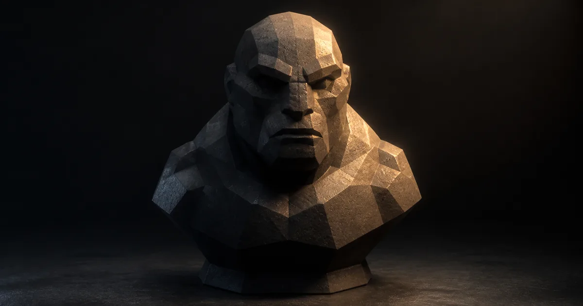
Shadow terminator artifacts are the scalloped, faceted, or dimpled bands that appear where direct light turns into shadow on a smooth-looking low-poly surface. The mesh may carry a flawless material and beautifully interpolated normals, yet a moving sun reveals every triangle as if wireframe mode had developed stage fright.
The renderer is not forgetting to smooth the object. It is answering two different questions with two different surfaces. Shading normals describe an idealized curve for lighting. Geometric triangles decide whether a point can see the light. Near the terminator, those answers diverge.
This guide explains the shadow terminator problem, separates it from shadow acne and banding, and gives a production order for fixes in Blender, Unity, and Unreal Engine.
Shadow terminator artifacts come from two normals
Every triangle has a geometric normal derived from its actual vertices. Smooth shading interpolates vertex normals across that triangle, producing a shading normal that changes gradually from pixel to pixel. The lighting term may treat the coarse surface as a curve even though the visibility system still traces or samples the real faceted mesh.
At the light-dark boundary, a geometric face can already be turned away from the light while part of its interpolated shading normal still points toward it. Direct lighting says “lit”; the visibility test says “blocked.” The disagreement appears as shadow terminator artifacts that follow triangle size and orientation.
shading: max(dot(N_shading, L), 0) | visibility: real triangle surface
This is why the issue survives higher shadow-map resolution and ray tracing. Better visibility makes the real geometry more accurate; it does not turn a twelve-sided sphere into the curve suggested by its normals.
Recognize low-poly shadow artifacts before tuning bias
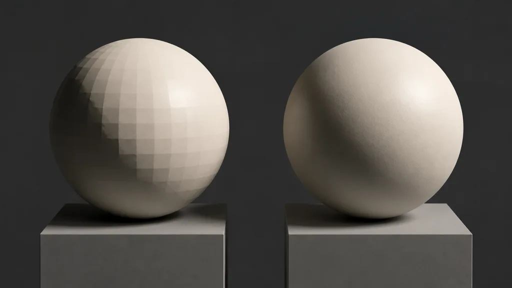
Low poly shadow artifacts are easiest to diagnose with one hard directional light, neutral rough material, no normal map, and limited ambient fill. Rotate the light slowly. A shadow terminator fault moves around the curved form and breaks according to polygon structure.
Do not confuse it with nearby problems:
- Shadow acne creates repeated self-shadow dots, stripes, or moiré from depth precision and insufficient bias.
- Peter-panning detaches a cast shadow from its object because bias is too large.
- Normal-map faceting stays in the lit response and may track UV seams, tangent errors, or compression.
- Color banding forms smooth tonal steps from limited precision or post-processing, not triangle-shaped bites.
- LOD popping changes suddenly at a distance threshold; the terminator itself may be correct within each LOD.
Switch between flat and smooth shading. Flat shading exposes the real faces everywhere. Smooth shading hides them in the lit region but leaves a broken boundary. That contrast is strong evidence for geometry normals vs shading normals, not a texture fault.
Fix shadow terminator artifacts with geometry first
The best answer is also the least glamorous: add enough geometry for the silhouette and lighting scale. Subdivide broad visible curves, improve the near-camera LOD, or redirect topology so long thin triangles do not cross the expected terminator. You do not need uniform density. Spend triangles where curvature, light, and screen coverage make the mismatch visible.
A practical fix shadow terminator artifacts pass:
- Freeze a diagnostic light. Use a hard grazing source and capture the bad angle.
- Inspect real curvature. Enable wireframe and find faces spanning too much change in surface direction.
- Add support locally. Subdivide the offending arc, bevel a broad edge, or replace a coarse LOD near the camera.
- Recalculate normals. Remove accidental hard edges, inverted faces, and weighted normals that overstate curvature.
- Check every LOD. A clean hero mesh is irrelevant if LOD1 becomes a gemstone under the sun.
- Restore displacement and normal detail. Confirm production maps do not reopen the gap.
- Apply bias only to the residue. Use the smallest setting that survives motion.
Mesh density should reflect final camera distance. A background pebble does not deserve film geometry. A vehicle hood crossing a sharp sun does. The triangle budget is not moral philosophy; it is screen-space evidence.
Normal maps cannot repair the occluding surface
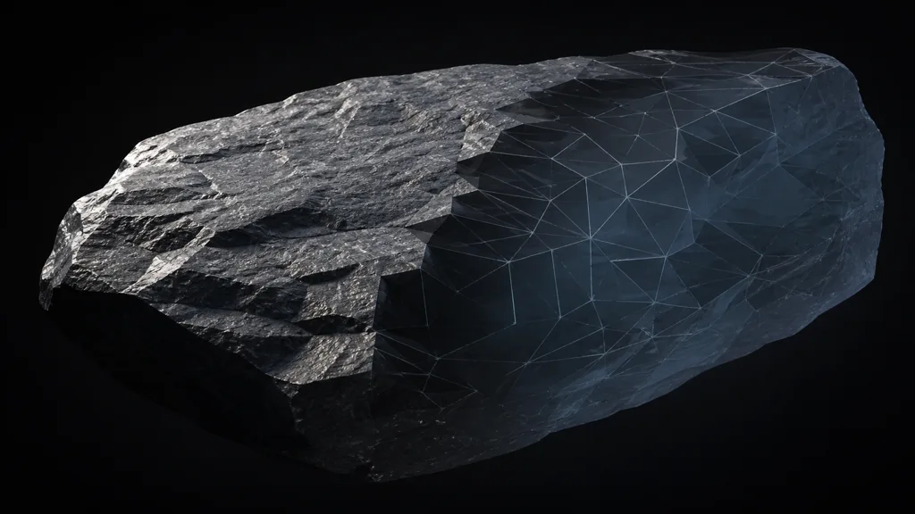
A normal or bump map changes N_shading. It does not move the triangle that blocks the light. Strong detail can therefore worsen smooth shading shadow artifacts: the visible lighting bends farther from the geometric surface while the shadow test remains fixed.
Weighted normals also need restraint. They can make large faces read cleanly by borrowing direction from surrounding geometry, but on a very coarse curved object they may increase the angle between shading and geometric normals. Use them to improve a plausible mesh, not to impersonate missing curvature.
True displacement or tessellation can help because it changes geometry before visibility is evaluated. Confirm when displacement occurs in the target renderer, which LOD owns it, and whether shadow passes use the displaced surface. Parallax and parallax occlusion mapping alter surface appearance without necessarily changing the shadow caster.
Shadow terminator bias trades one error for another
A renderer can offset a shadow ray, receiver position, or normal-based lookup so the visibility boundary better matches smooth shading. This shadow terminator bias is useful when geometry cannot change, but it is a controlled cheat.
Too little bias leaves the faceting. Too much can shrink cast shadows, detach contact, erase small creases, or leak light through thin parts. Global bias is especially expensive because one low-poly prop can force every detailed surface to accept a worse answer.
A larger physical light softens the terminator and often makes the fault less visible. That is valid when the source should be large. Changing a noon sun into a studio softbox only to protect a twelve-triangle shoulder is lighting art direction by hostage negotiation.
Prefer this order: geometry, normals, correct LOD, physically intended source size, then local bias. After any bias change, inspect contact shadows, thin walls, overlapping parts, and distant detail.
Shadow terminator fixes in Blender, Unity, and Unreal
For shadow terminator Blender work, Cycles exposes per-object Shadow Terminator controls. Blender's current manual recommends Geometry Offset because it affects lighting less than Shading Offset; the latter shifts the boundary more directly and is not energy conserving. Add geometry first, then raise Geometry Offset only enough for the target shot.
For shadow terminator Unity work, inspect the mesh and LODs before touching light bias. Unity's Light.shadowNormalBias offsets directional-light shadow casting along normals; larger values can make the shadow shape smaller. Tune it per representative light and test for leaks. It is a shadow-map control, not a replacement for curved geometry.
For shadow terminator Unreal Engine work, Epic's Virtual Shadow Maps documentation identifies the same low-poly geometry versus smooth-normal mismatch and recommends more polygons or a higher-detail LOD first. With VSM, r.Shadow.Virtual.NormalBias is a fallback; increasing it can remove the artifact while losing fine shadow detail elsewhere.
Across engines, compare raster shadows, ray-traced shadows, and unshadowed direct lighting when available. If multiple visibility methods show the same triangle-shaped boundary, the asset is telling the truth about its geometry.
Validate the fix under hostile light
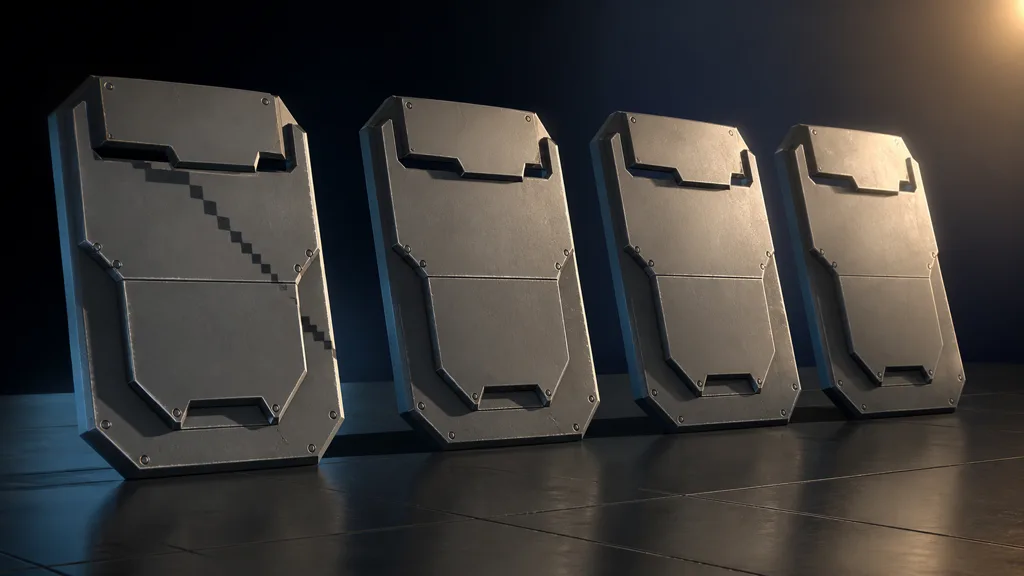
The best shadow terminator fix 2026 survives a test matrix:
- rotate a hard directional light through a full arc;
- test a small point source and a broad area source;
- move the camera from hero distance through every LOD transition;
- compare flat normals, smooth normals, weighted normals, and production normal maps;
- toggle bias off and on while watching thin and contact-shadow geometry;
- inspect both rough dielectric and smooth specular materials;
- capture motion, because a crawling terminator is easier to see than one favorable frame.
Record the winning mesh revision, normal export policy, light settings, renderer mode, and bias. Otherwise the artifact will return during optimization wearing the helpful name “LOD improvements.”
Try CraftPBR
CraftPBR gives shadow terminator artifacts a clean material context for diagnosis:
- Text-to-PBR generates aligned base color, normal, roughness, height, AO, and metalness from a material brief.
- Photo-to-PBR turns controlled surface evidence into editable maps without baking room light into the result.
- Node workspace lets you reduce normal strength, isolate roughness, tune height, and remove texture variables from the test.
- Engine export prepares normal orientation, channel packing, color-space intent, and target-friendly names.
- Free tier lets you build and test a complete material before spending budget.
- CC0 output lets you edit, bake, render, and ship generated textures without attribution.
A texture can explain a surface. It cannot submit extra triangles on the mesh's behalf.
Build a test-ready PBR material →